System schemetic – CNB SDF1212 User Manual
Page 7
7
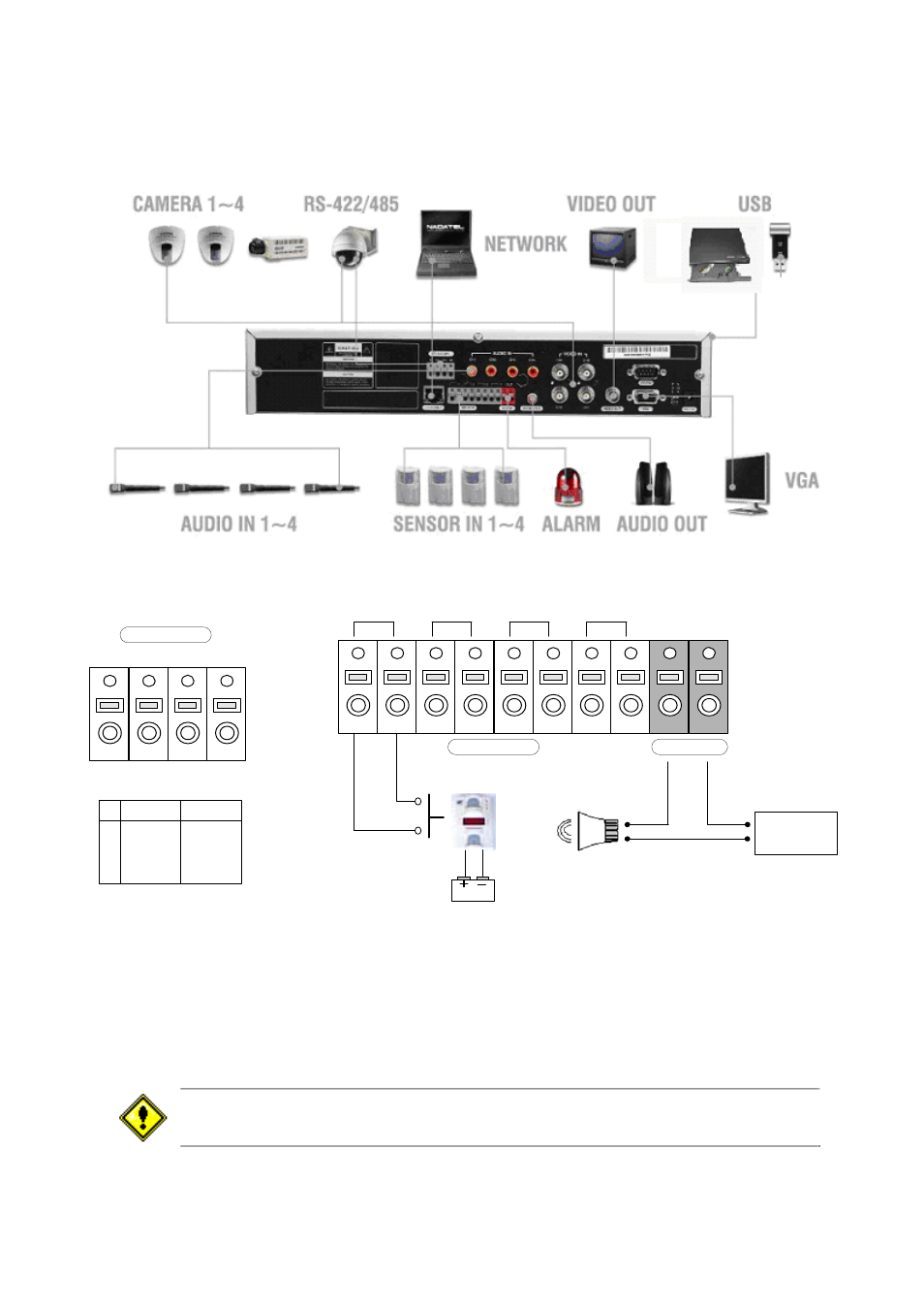
SYSTEM SCHEMETIC
Wiring Camera Control port and Sensor input / Alarm output
Dried Contact
1
2
3
4
OUT
(+)
(-)
(+)
(-)
+12VDC
ALARM
SENSOR
Sensor
Adapter
RS-422/485
TX+
TX- RX+ RX-
1 2 3 4
RS422 R485
1 TX+ DATA+
2 TX- DATA-
3 RX+
4 RX-
SENSOR INPUT :Connect two signal lines of sensor (infrared rays sensor, heat perception sensor, magnetic
sensor) to the desired sensor number.(You can set the type-NC or NO- of sensor at “Setup” mode).
ALARM OUTPUT : Use this at 30V/300mA or less operating voltage and current.
When controlling lamp and AC operated equipment, control it using separate outside relay.
During normal operation the control output contact is maintained at “Open” status, and during
control output the output contact is changed to “Close(short)” status.
SENSOR inputs need dried contact only. Do not input any electric signal.