Cleveland Motion Controls ULTRA ISC CARTRIDGE TRANSDUCER REV AA User Manual
Page 20
U
LTRA
S
ERIES
S
TATIONARY
S
HAFT
T
RANSDUCER
T
ECHNICAL
M
ANUAL
MAN-70430-0
R
EV
AA
12
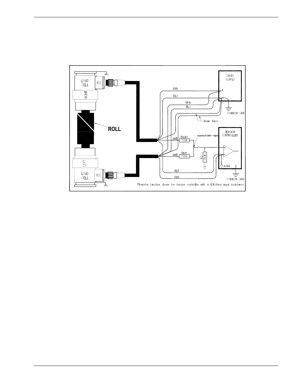
In the following schematic using the resistance values shown, the equation for the summed signal is:
V
sum
= 2/5 (V
left
+ V
right
)
The resultant voltage for 10 volts applied to V
left
and V
right
would therefore be 8V.The maximum load
experienced by each loadcell’s output stage would be 7.5K ohm, necessitating that each loadcell amplifier
be capable of 1.3 mA of load current.
Figure 8 ISC Summing Amplifier