3 cabling – Cleveland Motion Controls ULTRA ISC CARTRIDGE TRANSDUCER REV AA User Manual
Page 16
U
LTRA
S
ERIES
S
TATIONARY
S
HAFT
T
RANSDUCER
T
ECHNICAL
M
ANUAL
MAN-70430-0
R
EV
AA
8
In environments with severe electromagnetic noise, it may be necessary to route the cables inside
metallic conduit.
Polarity changes are accommodated by reversing the physical orientation of the transducer, by
interchanging the black and white output wires, or by changing the settings in the user’s
application software.
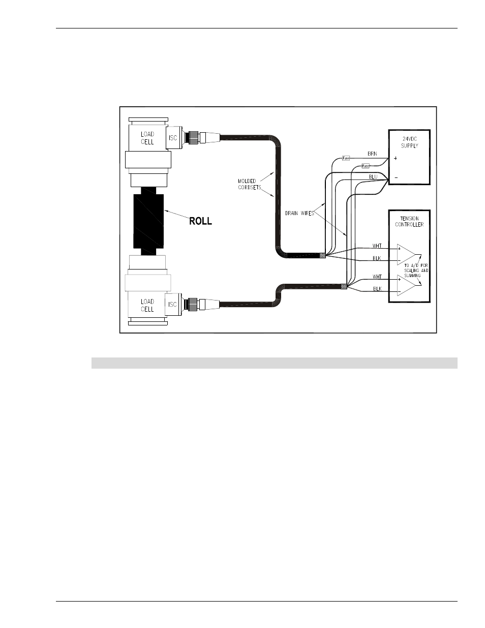
Figure 6 Installation Wiring Diagram
2.3 Cabling
Important: Most start-up problems are the result of mis-wiring or failure to reference the detailed
information in this manual. Additional information details can be found in the subsequent sections of this
manual and should be referenced before actual installation begins.
The connector for the ISC is a standard 4-pin M12 quick-connect connector keyed for DC operation.
Molded cordsets are readily available (see Table B) that can provide a direct connection between the ISC
equipped Tension Transducer, the required 24 VDC supply and tension controller (PLC, Tension Indicator,
Analog Input Module, etc). Ready-made PUR (polyurethane) jacketed cordsets are available in different
lengths and different connector orientation (straight or right-angle) from Cleveland Motion Controls. It is
advisable to employ an overall outer shield (or place cable in a metallic conduit) for noise rejection in
environments with high levels of electromagnetic interference.
The wire gage should be a minimum of 24 AWG to aid in minimizing undesirable voltage drops. An
overall outer shield is required, with the shield connected to ground at the tension controller through as
short a connection as possible. The short connection is essential in minimizing parasitic inductance and
thereby maximizing the shielding effectiveness at high frequencies.
Exercise care in routing the cable to minimize electromagnetic interference from noise generating wiring
and equipment.