1 m12 mating connector, 2 electrical connections and wiring – Cleveland Motion Controls ULTRA ISC CARTRIDGE TRANSDUCER REV AA User Manual
Page 15
MAN-70430-0
R
EV
AA
U
LTRA
S
ERIES
S
TATIONARY
S
HAFT
T
RANSDUCER
T
ECHNICAL
M
ANUAL
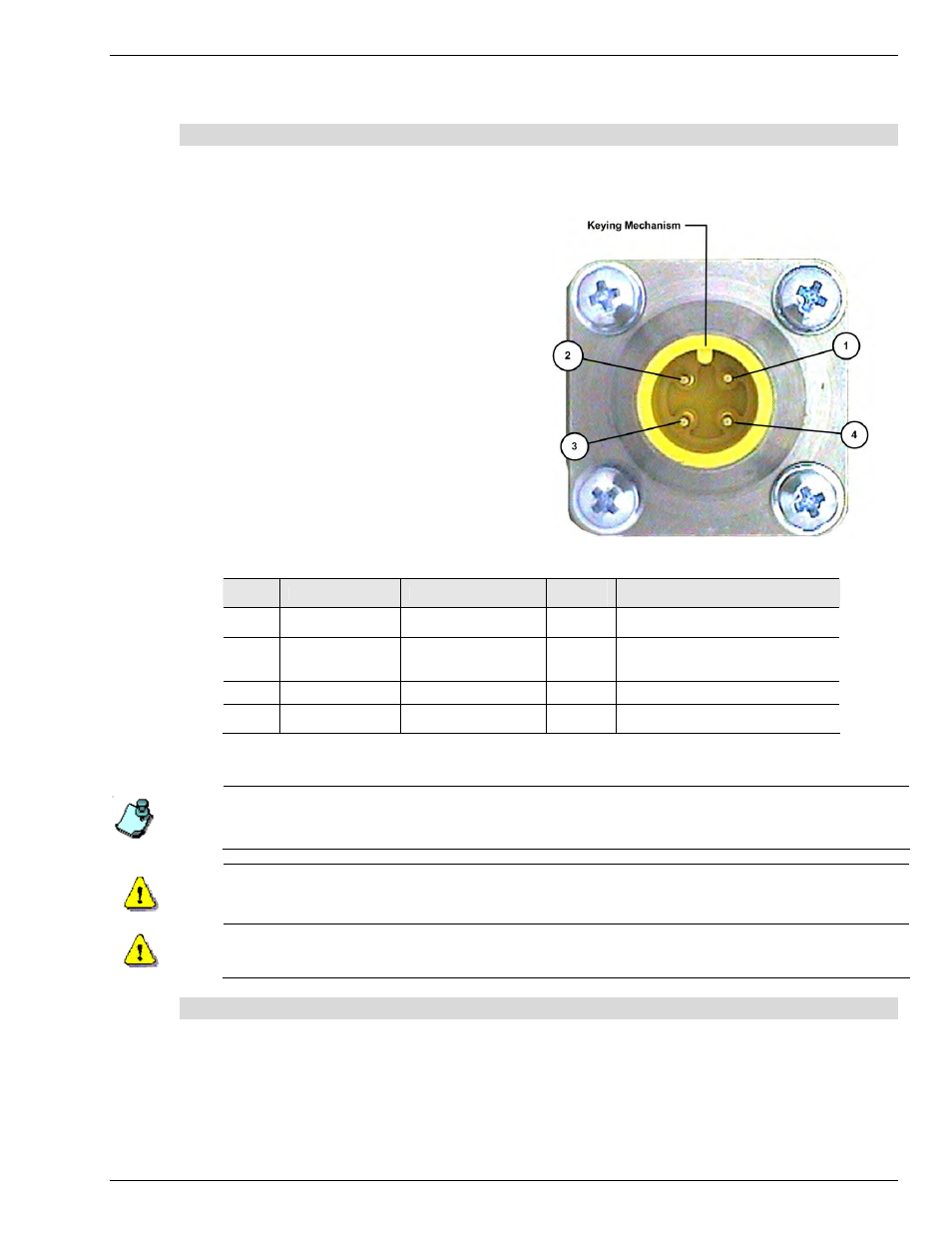
2.1 M12 Mating Connector
The M12 connector used on the Ultra Series ISC amplifier is a four-pin, DC keyed, male connector that
mates directly with the molded cordset offered by Cleveland Motion Controls. Table A lists the pin
numbers, signal, Function, wire colors and any notes that apply:
When mating the connector, align the keying
mechanism and pins so that they enter the
socket without you having to apply excessive
force. Use your fingers to sufficiently tighten
the coupling nut enough to ensure an adequate
seal and to discourage accidental loosening.
Figure 5 - Front View of M12 Connector
Pin #
Signal
Function
Wire
Color
Notes
1 +24
VDC
Power Supply source
24 Vdc
Brown
+24 VDC
@ 50 mA max
2
+/- 10V OUT
Voltage Signal Output
Undamped bi-polar
tension signal
White
max. load 2 mA
3
0V RET
Power Supply Return
Blue
Must not exceed 25 volts from P.E.
4
COMMON
Signal Output Return
Black
Common for +/- 10V analog output;
Must not exceed 25 volts from P.E.
Table A M12 Pin Numbers and Cable Colors
If you choose to make your own cables or need to repair damaged connectors, you can purchase a separate mating
connector from Cleveland Motion Controls. To order, use CMC part number, X43-34338.
A fuse with a rating of 0.25A must be used in the fixed 24 VDC supply lead to limit potential damage to the
amplifier in the event of circuit malfunction. Example: Bussman GMA-250-R
Transducers (load cells) use strain gages which have limited insulation levels to ground (earth). This
requires that the COM terminals be referenced to ground (earth) to prevent damage to the transducers
(load cells).
2.2 Electrical Connections and Wiring
Refer to Figure 6 Installation Wiring Diagram for making the transducer to power supply and tension
controller connections. Make certain that:
The cables do not interfere with the web path, and that they are away from power transmission,
gearing or other moving parts.
You exercise care when routing the cables to avoid pick-up from noise-radiating power cabling
(motor armature leads, AC mains wiring, etc).
7