Installing in-linelinc dimmer – INSTEON In-LineLinc Dimmer (Dual-Band) (2475DA1) Manual User Manual
Page 5
Page 5 of 14 2475DA1 - Rev: 1/21/2014 7:52 AM
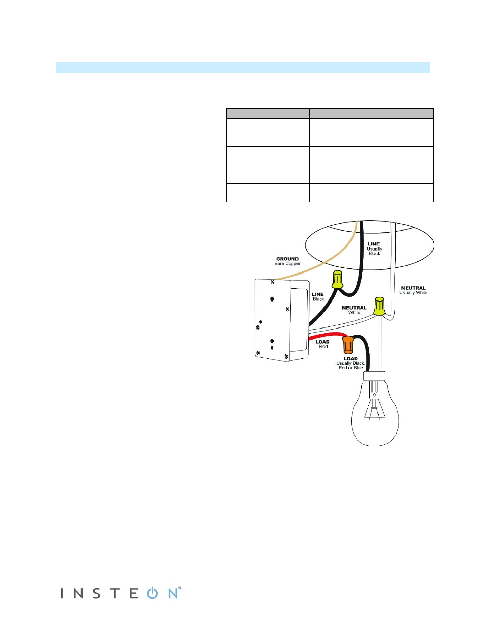
Wiring Diagram
NOTE: Home’s wire colors
and locations may vary
Installing In-LineLinc Dimmer
1) At electrical panel, turn off circuit breaker(s) and/or remove fuse(s) feeding wall box. Verify the power
is off.
2) Remove the fixture’s wallplate, unscrew the fixture and pull it out from the junction box.
3) Disconnect the wires from the fixture and
ensure that you have ½” of bare wire on
the ends.
4) After ensuring wires are not touching, turn
breaker(s) back on.
5) Use a voltage meter to identify the Line
and Load wires connected to the fixture,
then identify Neutral and Ground wires.
6) Turn off breaker(s).
7) Connect wires according to the wiring
diagram below. Confirm there are firm
attachments with no exposed wire.
8) Prior to reinstalling the fixture, turn on circuit
breaker supplying power to the fixture.
9) Use In-LineLinc Dimmer’s ON and OFF buttons
to test load control.
10) Add In-LineLinc Dimmer to scene(s) as a
responder to desired INSTEON devices.
11) Turn off breaker(s).
12) Gently place In-LineLinc Dimmer into the junction
box, making sure nothing could accidentally
press any of the buttons on its face.
13) Reinstall the fixture.
14) Turn on breaker(s).
In-LineLinc Wire
Wall Box Wires
Bare copper
Ground
(commonly bare green wire or
green screw)
White
Neutral
(commonly white wire bundle)
Red
Load
(Light, etc.)
Black
Line
(100 - 277V to Neutral)