9 system setup menu, Operation – Hach-Lange SC 60 User Manual
Page 39
35
Operation
4.9 System Setup Menu
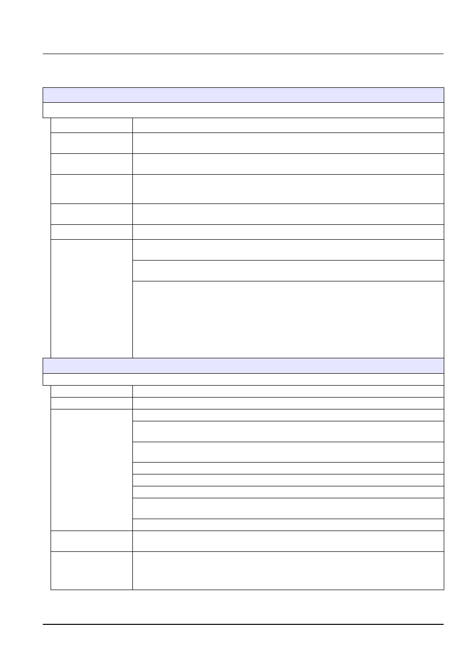
OUTPUT SETUP (see
section 4.5.1 on page 32
for expanded menu information)
SELECT OUTPUT 1 OR 2
SELECT SOURCE
Press
ENTER
to display the name of the sensor that will drive the output.
SET PARAMETER
Press
ENTER
to select from the displayed parameters. Highlight the appropriate displayed
parameter and press
ENTER
.
SET FUNCTION
Select LINEAR CONTROL for current output to track the measurement valve. Select PID
CONTROL for the sc60 to operate as a PID controller.
SET TRANSFER
Each analog output is normally active, responding to the measured value of its assigned
parameter. However, during calibration, each output can be transferred to this preset
transfer value.
SET FILTER
Average measurements over time (0–999 seconds). Default is 0 seconds. The higher the value,
the longer the sensor signal response time will be to a change in the actual process value.
SCALE 0 mA/4 mA
Select 0 mA or 4 mA for minimum current (outputs will be set to 0–20 mA or 4–20 mA).
ACTIVATE
Dependent on Function selected previously. See
section 4.5.1 on page 32
for
additional information.
FUNCTION set to LINEAR CONTROL: If LINEAR CONTROL was selected in SET FUNCTION,
set the low and the high values for the current output here.
FUNCTION set to PID CONTROL
SET MODE: AUTO or MANUAL.
PHASE: DIRECT or REVERSE controller operation.
SET SETPOINT: Enter the setpoint the PID control will control the process to.
PROP BAND: Control the proportional band for the PID control.
INTEGRAL: Control the integral action time period in minutes.
DERIVATIVE: Control the settings for the rate control.
RELAY SETUP
Select Relay A, B, or C
SELECT SOURCE
Select from none, the connected sensor, or the real time clock (RTC).
SET PARAMETER
Press
ENTER
to select from the displayed parameters.
SET FUNCTION
Source set to sensor
Alarm: Operates relays in response to the measured parameter. Contains separate High and
Low Alarm points, deadbands, and ON/OFF delay.
Feeder Control: Operates in response to the measured parameter. Can be set for phasing,
setpoint, deadband, overfeed timer, and ON/OFF delay.
Event Control: Controls a cleaning system (or equivalent) on a timed basis.
Warning: Activated when the analyzer detects a sensor warning.
PMW Control: Allows the relay to provide a duty cycled output.
Freq Control: Allows the relay to cycle at a frequency between the minimum pulse per minute
and maximum pulse per minute.
Source set to RTC
SET FUNCTION
Timer: Sets the timer for a cleaning system (or equivalent). Controls the output hold, interval,
duration, and off delay.
SET TRANSFER
Sets the relay to Energize or De-energize (user-selectable). Normally, each control or alarm relay
is active, responding to the measured value of its assigned parameter. During calibration,
however, the relay can be transferred to a preset on/off state to suit the application requirements.
Select Energize or De-energize and press
ENTER
.