Cashco 987 User Manual
Page 7
7
IOM-987
11. Remove seat ring O-ring seal (5) from seat
ring (3). Inspect O-ring (5) for signs of failure
to seal, then discard.
12. Remove body (1) from vise and place body
(1) and seat ring (3) into a suitable cleaning
sol vent.
13. For valves equipped with Opt-27 Viscous
Service Bonnet, ensure that the two equal-
iz ing passageways located in bonnet (2) are
fully open.
14. For valves equipped with a composition seat
as a part of the plug/stem sub as sem bly (4), the
parts are mechanically pressed together such
that the com po si tion seat is non-re place able.
A new plug/stem subassembly (4) must be
sup plied in order to replace the com po si tion
seat.
15. After soaking, remove all parts (1,2,3,4,7,11)
and inspect for any signs of wear or cor ro sion;
replace all worn parts with new parts. Bonnet
(2) pack ing box and stem (4) sealing zones
must be fi nished to a 16R
a
surface or better.
16. Place body (1) into a vise with bonnet-zone
on topside.
17. Place a new O-ring seal (5) onto the seat ring
(3). Reinstall the seat ring (3) into the body (1)
by rotating the seat ring (3) CW (viewed from
above). Using the steel bar tool, fi rmly tighten
the seat ring (3). NOTE: Do not over-tighten
the seat ring (3) to prevent galling of threads.
18. Place a new O-ring seal (6) into the bon net's
(2) recess in the body (1).
19. Place TFE sealant tape over threaded-end of
stem (4), cov er ing all the peaks.
20. Place plug/stem subassembly (4) with the plug-
end into the seat ring (3), and the thread ed-end
directed upwards. Place lower end of bon net
(2) over thread ed end of stem (4) and fully
lower bonnet (2) until prop er ly aligned in body
(1) recess.
21. Place bonnet fl ange (7) over bonnet (2) and
down over the bonnet studs (8), align match
marks.
22. Install bonnet fl ange nuts (9) and fi nger-tight en.
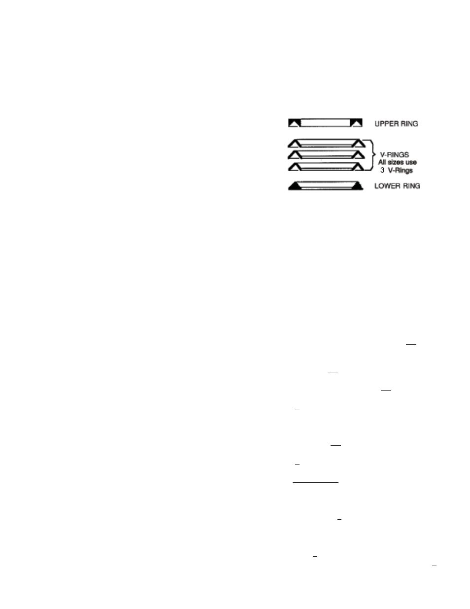
23. See Figure 5. Place a lower adapter packing
ring (10.1) over the stem-end (4) and press
it into the bonnet (2) packing box using the
pack ing follower (11). Repeat for the three
middle packing v-rings (10.2). Press upper
adapter ring (10.3) into the box; leave the
pack ing fol low er (11) in po si tion.
Packing Orientation
24. Wiggle stem (4) around to align parts
(2,3,4,7,10) as much as possible. Wrench-
tighten bonnet fl ange nuts (9) equally with a 1/4
turn revolution each, in alternating, cross-
pat tern. Using a torque wrench, tighten the
nuts (9) to 25 - 30 ft-lbs (33.8 - 40.6 N•m).
25. Using hand pressure, push plug/stem (4)
assembly down into the body (1) until the
plug touches the seating surface in the body.
Remove TFE tape from threaded end of
stem (4).
26. Raise Model C27or C53 actuator (AA) above
the threaded end of the stem assembly. Use
matchmarks from B.1. previous to assist with
(BA) and (AA) alignment.
27. Lower actuator assembly (AA) until the valve
stem (4) penetrates the opening in the yoke
(3). Re po si tion the “dangling parts” - packing
fl ange (23), yoke nut (15), ac ces so ry plate
((AP)) and in di cat ing washer (16) - over the
body stem (4). Con tin ue to lower the actuator
assembly (AA) until there is ap prox i mate ly
1/4" (6 mm) space between the two stems
(6) (4).
28. For ATC-FO: Connect a temporary air supply
hose that has an ad just able airset with gauge
to the ac tu a tor inlet to allow pres sur iza tion.
Slowly pressurize actuator to bring the ac-
tu a tor stem (6) to be with in 1/8" (3 mm) of
contacting the valve stem (4).
29. With hand lift stem (4) up to touch ac tu a tor
stem (6). Rotate valve stem (4) CCW (viewed
from above) to en gage w/ ac tu a tor stem (6).