Cashco 987 User Manual
Page 3
3
IOM-987
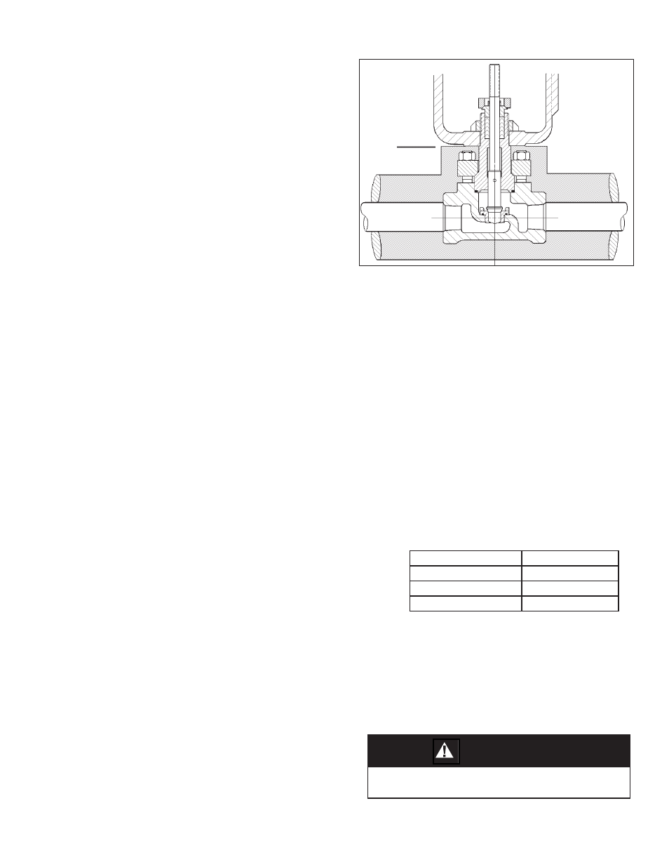
Figure 2: Body Insulation
Limit of
Bonnet
Insulation
9. Flow Direction: Install so the fl ow direction
match es the arrow marked on the body.
10. For best performance, install in well drained
hor i zon tal pipe, properly trapped if a steam
service ap pli ca tion.
11. Valves are not to be direct buried un der ground.
12. Insulation may be applied as indicated in Fig-
ure 2. Drainage away from the packing area
must be ensured when fully installed, sealed
and lagged for outdoors installation.
13. Undue piping stress/strain or bending torques
may not be transmitted through the control
valve body. One pipe (inlet or outlet) should
be anchored rigidly for piping that is “hot” or
“cold” with respect to ambient temperature;
the re main ing pipe (inlet or outlet) should be
supported and guided to ensure uni di rec tion al
expansion/con trac tion.
C. Air Supply:
1. Use a desiccant dried, instrument quality air
supply. Such a supply is recommended for
outdoor installations, and is required in areas
of freezing weather conditions.
2. If air supply contains moisture and /or lubri-
cating oil, the air should be fi ltered with a
coalescing type of fi lter prior to use in stroking
the actuator.
3. Failure to remove moisture will cause corrosion
to the internals of the actuator casings.
4. Connections for the air supply are 1/4" female
NPT. Use a suitable pipe thread sealant when
installing the pipe or tube fi tting. DO NOT al-
low sealant to enter the tube/pipe.
SECTION IV
IV. STARTUP
A. General:
1. Ensure that the Model 987 unit has been
properly adjusted and calibrated, including
the positioner if installed.
2. Recommend startup to be in a “manual” mode.
This procedure assumes double block (iso la-
tion) and bypass valves for the “control valve
station”. See Figure 1.
3. Start with either of the two block valves closed,
with the other open. The bypass valve should
be closed. Pressurize system if possible/
prac ti cal.
4. Back out the airset's adjusting screw until
loose.
5. Turn on air supply pressure.
6. Adjust the air supply airset (fi lter-regulator)
to the proper level as indicated as follows:
Bench Setting
Airset Output
psig (Barg)
psig (Barg)
5–15 (.34–1.0)
20 (1.4)
15–60 (1.0–4.1)
75 (5.2)
7. Place loop controller into “manual” mode.
Vary setting from minimum – mid-range –
max i mum SIG output. Observe response of
con trol valve unit to these changes of input
SIG. The valve should fully stroke at the varia-
tion from minimum SIG to maximum SIG; the
mid-range SIG should have the valve stem
travel at/near 1/2 open.
CAUTION
DO NOT WALK AWAY AND LEAVE A MANUALLY CON-
TROLLED CONTROL VALVE UNATTENDED!