Caution, Warning – Cashco 987 User Manual
Page 2
2
IOM-987
B.
Piping
System:
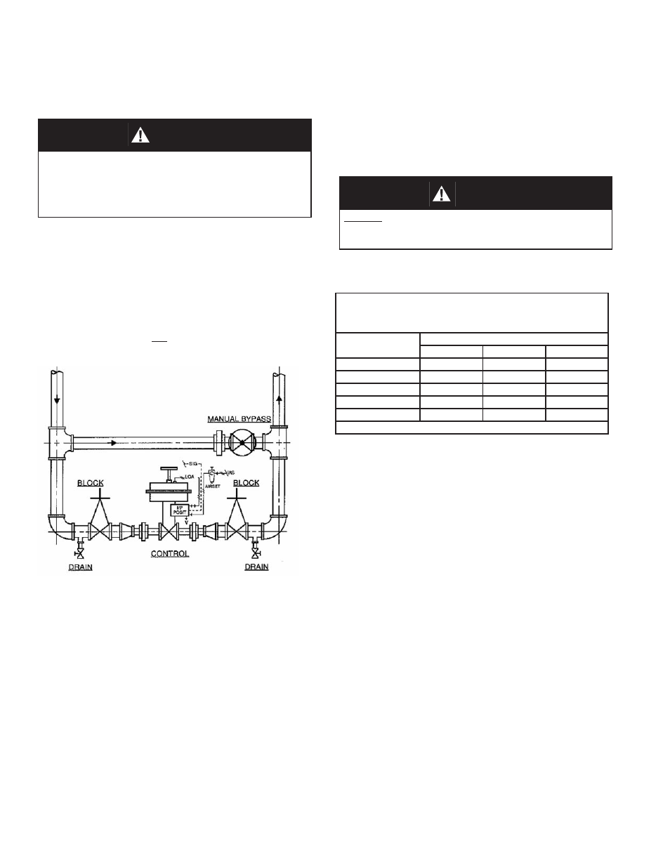
1. It is recommended that the control valve unit
be installed with a double-block and bypass
as indicated in Figure 1. This arrangement is
recommended especially where main te nance
will be done on the valve body while still in-
stalled in the pipeline.
2. Pipe unions are recommended for NPT
screwed in stal la tions to allow complete re-
mov al from system.
3. If pipe reducers are located before and/or after
the valve body, keep the reducers as close as
Figure 1: Typical Control Valve Station
1. Recommended orientation when installed in
a hor i zon tal pipeline is with the stem verti-
cal. Valves may also be installed in vertical
pipe lines with stems horizontal.
2. Outdoors, all installations may be oriented
any angle from horizontal-to-vertical.
3. Valves are not recommended for in stal la tion
with the actuator oriented down wards.
SECTION III
III. INSTALLATION
A.
Orientation:
practical to the valve body; this is especially
important where the reducers are more than
one line size larger than the valve body size,
which is common in gaseous ser vice.
4. For
fl angeless installation, body (1) must be
machined with serrations on each end of body.
CAUTION
For welded installations, all internal trim parts and
seals must be removed from body prior to welding
into pipeline. The heat of fusion welding will dam age
non-metallic parts if not re moved. NOTE: This does
not apply to units equipped with extended pipe nip ples.
WARNING
DO NOT attempt to install a body machined for NPT end
connections as a fl angeless in stal la tion. Fail ure to heed
could cause fl uid leak age.
Model 987 bodies with fl angeless end con-
nections may be installed as below:
TABLE 1
PIPING FLANG ES & FLANGELESS
VALVE CONNECTIONS
Basic Flange
Size
Flange Pressure Class
150#
300#
600#
1/2"
N/A
N/A
N/A
3/4"
N/A
√
√
1"
√
√
√
1" x 1/2" Reducing
√
√
√
1" x 3/4" Reducing
√
√
√
√ Available
5. Opt-32 Extended Pipe Nipples should be used
for socket welding or butt welding. Standard
end preparation is for socket welding. If butt
weld ing is desired, weld end preparations must
be done in fi eld with suitable tools.
6. Clean the piping of all foreign debris, including
chips, weld scale, weld spatter, oil, grease,
sand or dirt prior to installing the control valve.
This is an absolute re quire ment for valves
supplied with composition soft seats. System
start-up strainers, for removal shortly after
initial start-up, are recommended.
7. Field hydrostatic testing the completed piping
system to 1-1/2 x CWP in psig indicated on the
nameplate, including the 987, is acceptable.
If hydro test pressure exceeds the 1-1/2 x
CWP limit, the 987 must be removed for such
testing. Before pressurization, the valve plug
should be lifted from the seat if of ATO-FC
action. Tighten packing as required.
8. In placing thread sealant on pipe ends prior
to en gage ment, ensure that excess material
is removed and not allowed to enter the valve
upon start-up.