Cashco Premier User Manual
Page 3
IOM-48
3
3. A 1/4"–NPT female connection for pneumatic
LOAD is located on the side of the actuator’s
upper diaphragm casing near the casing
fl ange joint. Reference specifi c Ranger-TB or
Pre mier-TB for location of the connection.
4. Reference the valve body instructions — IOM-
Rang er, IOM-Premier EZO or IOM-Premier
Unlined — for ad di tion al instructions on in-
stall ing unit in the process piping.
B. Air Supply:
1. Recommendation is that a desiccant dried,
instrument quality air supply be used. Such
a supply is recommended for outdoor in stal -
la tions, and is required in areas of freezing
weather conditions.
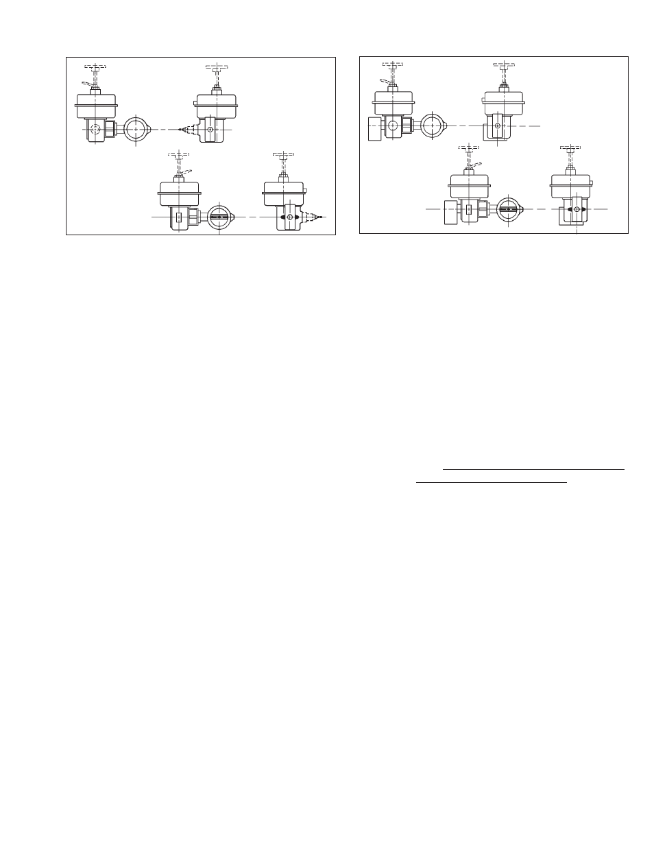
FIGURE 4: Mounting position of Premier EZO or Pre-
mier Unlined to Model 48 Actuator with Model 73N-B
P/P Positioner
FIGURE 5: Mounting position of Premier EZO or Pre-
mier Unlined to Model 48 Actuator with Models 9540R
or Smart Positioners
2. If air supply contains moisture and/or lu bri -
cat ing oil, the air should be fi ltered with a co-
a lesc ing type of fi lter prior to use in stroking
the actuator.
3. Connection for the air loading pressure is 1/4"
female NPT. A suitable pipe thread sealant is
recommended to be used when installing the
pipe or tube fi tting. Exhibit care to prevent the
sealant from getting inside the tube/pipe.
4. If an alternate gaseous fl uid is used as a source
of loading pressure (i.e. natural gas, ni tro gen,
etc.), this gas MUST NOT BE COR RO SIVE
to the aluminum casing material.
IV. OPERATION
A. General:
1. Actuators supplied with 5-13 psig (0.34-0.90
Barg) benchset range are designed to op er ate
with or without a positioner. A 3-15 psig (0.21-
1.03 Barg) instrument output signal would be
required to operate without a positioner.
2. On larger valve body sizes the benchset
range is essentially 1.5–2.3 times that of the
5-13 psig (0.34-090 Barg); i.e. 7.5-19.5 psig
(0.52-1.34 Barg) or 10-26 psig (0.69-1.79
Barg) for Model 148’s. Either a signal booster
or a positioner will be required for full rotation
(0°–90°) by the actuator.
SECTION IV
3. If an “installed characteristic” other than the
“inherent characteristic” is desired, a positioner
plus a “char ac ter iza tion cam” is required. The
inherent characteristic of Rang er QCT control
valves is linear; for Premiers the inherent
characteristic is equal percent.
4. See Tables 2 through 4 for available actuator
models with benchset ranges per valve type
and body size. (Note: Model 148 actuators
included for clarity.) Proper MAX I MUM air
supply pressures are also indicated.
Position A
Position B
Position A
Position B