Warning caution, Ranger qct – Cashco Premier User Manual
Page 18
IOM-48
18
Do not pressurize actuator assembly (AA) be yond the
“MAX ACTUATOR PRESSURE” level/value in di cat ed
on the unit’s nameplate (21). Fail ure to heed may
cause catastrophic failure of upper cas ing (1) lead ing
to fl ying parts.
WARNING
CAUTION
7. In this Section reference will be made to three
phrases –
a. “lower value of benchset range”,
b. “higher” value of benchset range”,
c. benchset
range.
The meaning of these phrases is sum ma rized
in the following table.
Benchset
Lower
Higher
Range
Value of
Value of
* Benchset
Benchset
Range
Range
5-15 psig
5 psig
15 psig
(.34-1.03 Barg)
(0.34 Barg)
(1.03 Barg)
* Identifi ed on nameplate (21) as “Bench” or “Input Range”.
B. Actuator Stem/Push Rod Adjustment:
1. Actuator stem/push rod linkage (8, 9, 10, 43,
43, 43, 44, 54) when properly ad just ed will-
a. Provide the proper benchset range.
b. Provide 90° rotation.
c. Provide proper valve stem (Ranger (7),
Premier (3.2)) “windup”.
2. Ensure that manual handwheel operator
(MHWO) has handwheel (58.1) backed fully
out by rotating CCW (viewed from above
handwheel (58.1)).
3. Remove cover plate (20) by removing four
screws (36).
4. Remove travel indicator dial (15), dial lens
(14), coverplate (13), bearing fl anges (19) and
bearing (18) by removing three cap screws
(31) using a 3/16" allen key wrench.
5. Units with ATO-FC (Reverse) Action:
a. Disconnect the lower L.H. rod end (9) from
en gage ment with the lever arms (5) by
removing shoulder bolt (40) and lock nut
(46). It will be necessary to re move stem
(Ranger (7), Premier (3.2)) “wind up” as
described in Sec tion V.B.4.
b. Swing the lever arms (5) down against
the travel stop screw (35); this “opens”
valve plug (6)/disc (3.1).
c. Loosen lower upstop jam nut (43) from
securing upstop washer (54); back nut
(43) to the root of its threads on push rod
(10).
d. The upper R.H. rod end (8), lower L.H. rod
end (9), and push rod (10) act to geth er as
a turnbuckle; the upper end is standard
right-hand thread ed while the lower end is
left-hand thread ed. To en sure max i mum
and equal en gage ment of rod ends (8,9)
to the push rod (10), it is rec om mend ed
that the link age (8,9,10) be fully en gaged
and then re ad just ed as a safety pre cau-
tion.
Unequal engagement adjustment of rod ends (8,9) and
push rod (10) can cause failure of a rod end (8,9)-to-
push rod (10) connection.
a. If this occurs during bench main te nance, the
parts (8,9,10) could snap apart and cause
per son al injury.
b. If this occurs during installed operation, con-
trol func tion would be lost.
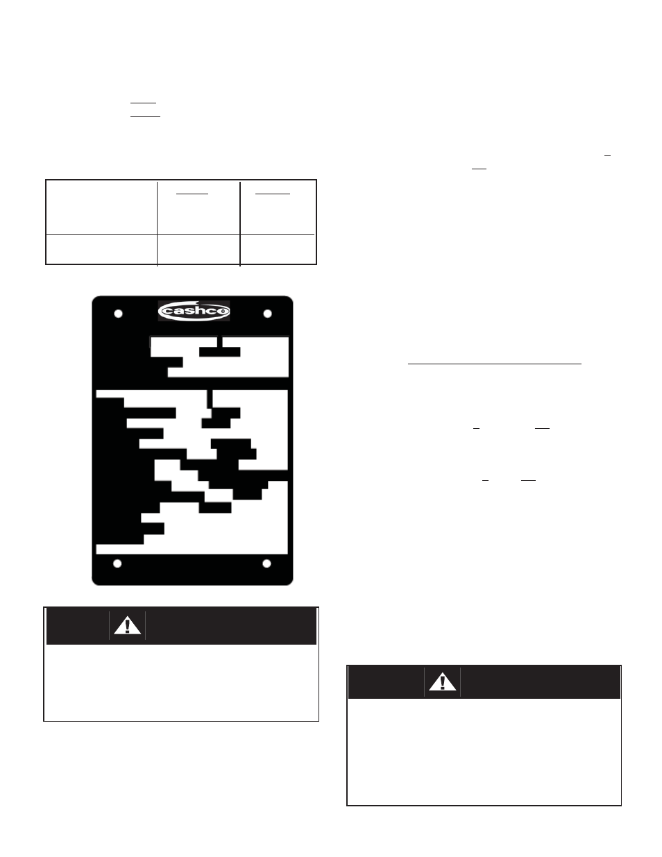
RANGER QCT
®
SERIAL NO.
BODY SIZE
MATERIAL
BODY RATING CLASS
END CON NEC TION
MAX ALLOWABLE WORKING PRESSURE
MAX.
MAX. WORKING ∆P
PSIG
PLUG
STEM
SEAT MATERIAL
PACKING
RATED Cv
INHERENT FLOW CHAR.
RATED Kv
RATED TRAVEL
TRIM NUMBER
FLOW TOWARD
FAILURE POSITION
OF PLUG
MTG. POSITION
PSIG
MAX ACTUATOR PRESSURE
INPUT RANGE
PSIG
OPTIONS
PRODUCT CODE
TAG NO.
PSIG @ 100°F
@ 38°C
90°
WARNING: REFER TO IOM PRIOR TO MAIN TE NANCE
CASHCO, INC.
ELLSWORTH, KS.
U.S.A.