Cashco Premier User Manual
Page 15
IOM-48
15
Benchset Range
Quantity
psig
(Barg)
of Springs
Array
5-15 (0.34-1.03)
6
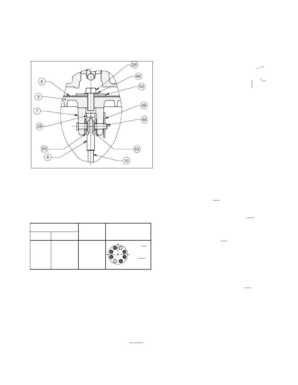
9. Inspect clevis (7), upper R.H. rod end (8), clevis
pin (48), washers (53) and hairpin (49) for signs
of looseness and/or wear; re place any worn
parts. Check bolting (26) for loose ness; tighten
as necessary to 15-18 ft-lbs (20-23 N-m).
Hub w/NO
Spring (11)
Hub With
Spring
(11)
Figure 12
Piston & Clevis Close-up
12. Reinstall a new diaphragm (6) and re as sem ble
the upper casing (1) as described in this Sec-
tion, V.E.12 through V.E.24.
13. Using air pressure of V.E.24., pressurize
the actuator upper casing (1) to the upper
value of the stated benchset range plus 2 psi
(0.14 Bar); i.e. for 5-15 psig (0.34-1.03 Barg)
benchset range, pressurize to 15+2 = 17 psig
(1.03+0.14 = 1.17 Barg). This pressure level
should cause the piston’s (3) lower skirt-edge
to bottom out on the lower casing (2).
14. Using only tools (i.e. no fi ngers within arm
housing (4)) to grasp the actuator stem/push
rod (10), insert push rod (10) with in ter con-
nect ed parts (9) (43) (43) (44) (54) into arm
housing (4) and engage into dangling upper
R.H. rod end (8) by rotating CW (viewed from
lower L.H. rod end (9)). Count number of
revolutions of push rod (10) en gage ment to
match those recorded in Article 4., previous,
at removal.
15. Release all air pressure into actuator upper
casing (1); remove air source from 1/4" FPT
connection.
16. Join the actuator assembly (AA) to the body
assembly (BA) as described in this Section,
V.I.
I. Joining of Body Assembly (BA) to Actuator
As sem bly (AA):
1. Determine proper orientation of actuator
(AA)-to-body (BA) for the following consid-
erations:
•
failsafe
action
• installed piping orientation.
Reference Sub-sections V.C. and V.D. to see
sche mat ics of orientations available.
2. Position body assembly (BA) on a fl at work
surface. Orient such that the actuator as-
sem bly (AA) can be ori ent ed with the top of
the actuator upper casing (1) on topside; i.e.
man u al handwheel operator sub-assembly
(MHWO) stem (58.2) vertically oriented, if
supplied.
3. Using an overhead hoist, lift the actuator
as sem bly (AA) (with position indicator ap-
pa ra tus (13,14,15,16,17,31,31,34), lever arm
ap pa ra tus (5,5,12,40,46,50,50), end-of-shaft
10. Place range springs (11) back onto hubs of
lower casing (2) per following table:
NOTE: Every spring (11) has another spring (11) 180°
across/opposite.
11. Aligning matchmarks of Article 7. above,
re po si tion piston (3) back onto top side of
range spring (11) array. Using a mirror tool
and fl ashlight, look through the rect an gu lar
open ing in the lower casing (2) from within the
arm housing (4) to ensure that the piston (3)
hubs are centered within the ID of the range
spring (11) coil. It may be necessary to use
a tool to move the upper end of the range
spring (11) as necessary to be “captured” by
a piston (3) hub. Each spring (11) MUST be
captured by a hub on top and bottom ends.