Hardware - connections, P sio 1, Cap1 – CAME Rbm84 User Manual
Page 8: Rbm 84, R em, R em p c 30, D ig ita l in p u t
Cap1
Hardware - CONNECTIONS
cap. <
1
> pag.<
8
>
ENGLISCH
REM
RBM84
REM
REM
REM
CAME
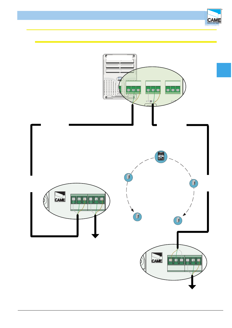
rbm84 connection <----> REMs (with two sections)
CAME
CAME
CAME
F
U
SE
630m
A
1
2
34567891
01
1
1
2
0
30
40
50
60
7
V
1
V
2V
3V
4V
5
C
ONT
R
O
L
B
OAR
D
P SIO 1
TR A N SFO R M ER TER M IN A L B LO C K
LIN E FU SE 5A
C A M E
U 2
R EM
R EM
P C 30
LT001
R 501/ 2
S5000
S6000
S7000
D IG ITA L IN P U T
1
2
3
4
TSP 00
LT001
S5000
S6000
S7000
TSP 00
R 501/ 2
N O
C
N C
N O
C
N C
N O
C
N C
N O
C
N C
N O
C
N C
N O
C
N C
N C
N O
C
N O
N C
C
L
N
om
A
B GND
A
B GND
A
B GND
RBM 84
RBM 84 - ELECTRICAL CONNECTIONS
from the next REM , for a maximum
of 60 units
(
INPUT AND OUTPUT CONNECTABLE ON TERMINAL
BOARD
1
OR
2
IN DIFFERENTLY
)
* the sum of the serial connected REMs
on the A+B section must be
60 units max.
tratta A*
Each REM is identifi ed by RBM84 through
a progressive number sequence (from 1 to 60)
irrespective of the position along the
connection cable route; this number (also called
address) must be set on the related
dip switch selector in the REM motherboard.
See Section 1, page 15
for the subsequent REM
(
INPUT AND OUTPUT CONNECTABLE ON TERMINAL BOARD
1
O
2
INDIFFERENTLY
)
Connection to two drawn: RBM84 can be in
any point of the run extracts
from the fi rst to thelast REM, the
distance (or the route
of the connection cable) must
be a maximum of 1,000 m
CANCELLI AUTOMATICI
CONTROL
BOARD
REM
2
1
S5000/S6000/S7000
1
2
A
B GND
1
REM
A
B GND
2
REM
CANCELLI AUTOMATICI
CONTROL
BOARD
REM
2
1
S5000/S6000/S7000
1
2
A
B GND
1
REM
A
B GND
2
REM
tratta B
Cable not included
type recommended:
shielded bipolar
min. 2 x 0.5 mm2
Cable not included
type recommended:
shielded bipolar
min. 2 x 0.5 mm2
from the next REM , for a maximum
of 60 units
(
INPUT AND OUTPUT CONNECTABLE ON TERMINAL
BOARD
1
OR
2
IN DIFFERENTLY
)