Hardware - connections, P sio 1, Cap1 – CAME Rbm84 User Manual
Page 7: Rbm 84 rem, R em, R em p c 30, D ig ita l in p u t
Cap1
Hardware - CONNECTIONS
cap. <
1
> pag.<
7
>
ENGLISCH
F
U
SE
630m
A
1
2
34567891
01
1
1
2
0
30
40
50
60
7
V
1
V
2V
3V
4V
5
C
O
N
T
RO
L
B
O
A
RD
P SIO 1
TR A N SFO R M ER TER M IN A L B LO C K
LIN E FU SE 5A
C A M E
U 2
R EM
R EM
P C 30
LT001
R 501/ 2
S5000
S6000
S7000
D IG ITA L IN P U T
1
2
3
4
TSP 00
LT001
S5000
S6000
S7000
TSP 00
R 501/ 2
N O
C
N C
N O
C
N C
N O
C
N C
N O
C
N C
N O
C
N C
N O
C
N C
N C
N O
C
N O
N C
C
L
N
om
A
B GND
A
B GND
A
B GND
CAME
REM
RBM84
REM
REM
REM
CAME
CAME
CAME
CAME
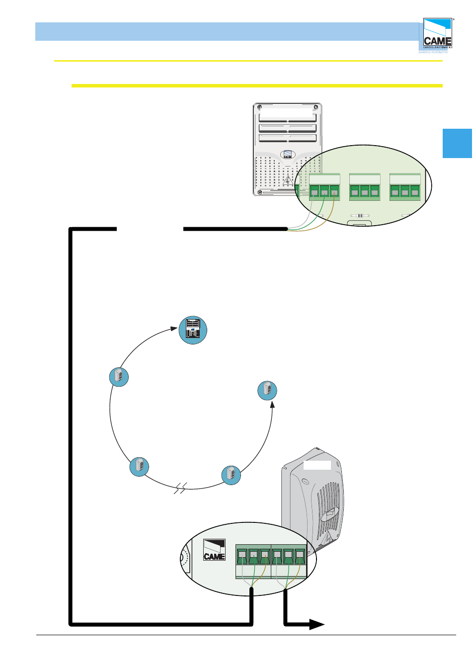
RBM 84
REM
from the next REM , for a maximum of
60 units
(
INPUT AND OUTPUT CONNECTABLE ON TERMINAL
BOARD
1
OR
2
IN DIFFERENTLY
)
Each REM is identifi ed by RBM84 through
a progressive number sequence (from 1 to 60)
irrespective of the position along the
the connection cable route; this number (also called
address) must be set on the related
dip switch in the REM motherboard.
See Section 1, page 15
from RBM84 to the last REM,
the distance (or the route
of the connection cable) must
be at most 1000 m
Connection to one draws: RBM84 is found to
the extremity of the run you extract
rbm84 connection <----> REMs (with one section)
CANCELLI AUTOMATICI
CONTROL
BOARD
REM
2
1
S5000/S6000/S7000
1
2
A
B GND
1
REM
A
B GND
2
REM
Cable not included
type recommended:
shielded bipolar
min. 2 x 0.5 mm
2
RBM 84 - ELECTRICAL CONNECTIONS