Software - system configuration, P sio 1, R em – CAME Rbm84 User Manual
Page 27: R em p c 30, D ig ita l in p u t
cap. <
2
> pag. <
12
>
ITALIANO
Software - SYSTEM CONFIGURATION
Cap 2
F
U
SE
630m
A
1
2
3
4
5
6
7
8
9
1
0
1
1
1
2
03
04
05
06
07
V1
V2
V3
V4
V5
C
ONT
R
O
L
B
OAR
D
P SIO 1
TR A N SFO R M ER TER M IN A L B LO C K
LIN E FU SE 5A
C A M E
U 2
R EM
R EM
P C 30
LT001
R 501/ 2
S5000
S6000
S7000
D IG ITA L IN P U T
1
2
3
4
TSP 00
LT001
S5000
S6000
S7000
TSP 00
R 501/ 2
N O
C
N C
O
A
N O
C
N C
N O
C
N C
N O
C
N C
N O
C
N C
N O
C
N C
N C
N O
C
O U T 1
A
B GND
N O
N C
C
O U T 2
A
B GND
L
N
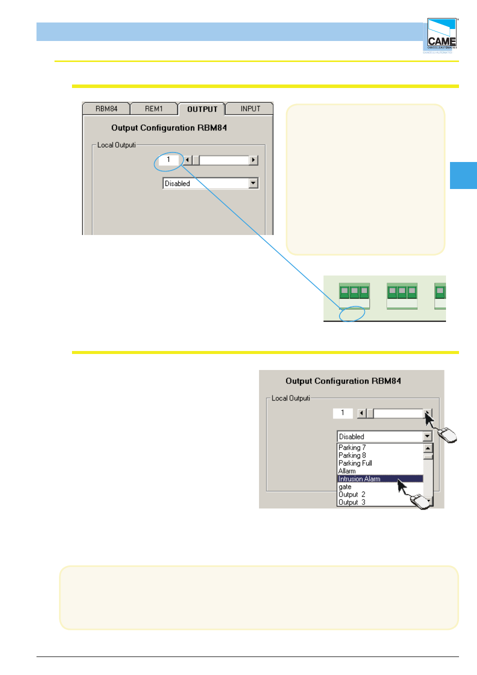
Select the output (1-8) and match it to one
of the names/devices appearing in the pull-
down menu
In the OUTPUTS board,
the outputs connected to RBM84 must
be programmed
with the function type and any activation
time
of the related relays;
If there are no automations connected,
select or leave “Disabled” as
suggested in the menu.
The output number corresponds
exactly to the number labelled on the
device connected to the
terminal board; see figure
In the pull-down menu of the Local Outputs area there appear (by default) the traffi c light exits and the
normal exits
as defi ned in Assign Exit Name
The exit device matching is independent of the physical connection of the latter on RBM84 or REM;
RBM84 -Software
Confi guring the outputs connected to RBM84
Activating the RBM84 outputs
1
2
1- Select the output (1-8)
2- And match it to one of the names/devices
appearing in the pull-down menu