Gardner Bender GMT-319 7 Function Analog Multimeter User Manual
Page 7
12
11
used for electrical troubleshooting around the
home, this function can be used to measure the
milliamperage draw of household items such as
flashlights, and other battery operated devices
that do not draw more than 500 mA. In fig. 2
the red (+) test lead is hooked up to the (+) ter-
minal of the lantern battery while the black (-)
test lead is hooked up to the bulb. The meter
will indicate the milliamperage draw when the
flashlight switch is thrown in the ON position.
Do not apply voltage to the
test leads while the meter is set in the
mA/A range. See #8
For Your Safety.
6. AC Voltage Measurement
1) Fully seat the test leads in the correct input
jacks (-) black lead, (+) red lead.
2) Set the function/range switch to the
appropriate AC voltage range. If the
voltage is unknown, use the highest range.
If the voltage applied falls within the range
of a lower setting, reset the function/range
switch to the appropriate setting for
greater accuracy.
3) Touch the test leads to the circuit under
test. With AC voltage, the polarity of the
test leads is not a factor.
Use the chart below as a guide to reading
AC voltage measurements:
AC V
Read
and
range
following
multiply
setting
scale
reading by:
10
0-10
1
50
0-50
1
250
0-250
1
1000
0-10
100
Common AC Voltage Measurements
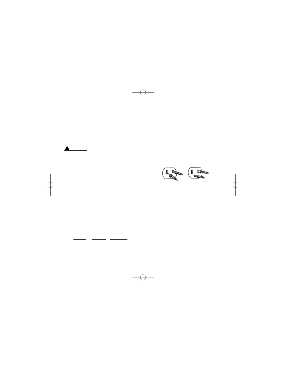
6.1 Wall Receptacles
If the receptacle is controlled by a switch, make
sure the switch is ON. Set the function/range
switch to 250V AC. Touch the test leads to the
“hot” and “neutral” slots of the receptacle (see
fig. 3A). The needle indicator should read 120V
AC on the 0-250 scale. To test for proper
grounding of the receptacle, touch one test lead
to the “hot” (narrow) side of the receptacle, and
the other test lead to the ground slot. The meter
should read 120V AC as before.
7. Resistance/Continuity Measurement
For resistance and continuity testing POWER
MUST BE OFF:
1) Fully seat the test leads in the input jacks (-)
black lead, (+) red lead.
2) Set the function/range switch to the appropriate
resistance and short the test leads together.
Using the zero ohms adjustment dial, slowly
turn the dial until the needle indicator reads -0-
ohms at the right end of the ohms scale. If the
needle will not zero, replace the internal batter-
ies with two new 1.5 volt AAA size non-
rechargeable batteries (see
Battery
Replacement).
3) Touch the test leads to the resistance or non-
energized circuit to be measured. Measure the
!
WARNING
Figure 3
3A
3B
GMT-319 manual 7.08.qxp 7/2/08 3:50 PM Page 12