Gardner Bender CO2 CONDUIT FISHING SYSTEMS User Manual
Page 6
2. Unfurl the Inflatable line carrier and place it in the conduit-bag
portion first (Refer to Figure 8).
3. In large conduit (4, 5, and 6” diameter), it may be necessary to
point the seal-off nozzle at the plastic sleeve of the Inflatable
to achieve initial inflation. This is accomplished by tilting the
seal-off in the conduit entrance. Otherwise the collapsed
Inflatable may allow the small diameter stream of CO2 to blow
past it.
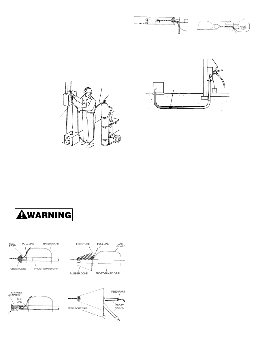
BLOWING PULL LINE IN THE CONDUIT
All CO
2
systems may be used to blow pull line or nylon line in the
Conduit. Position cart
transported cylinder
and pull line in a loca-
tion that will allow good
access to the conduit
entrance (Refer to Fig-
ure 9).
Set up as follows:
1. Connect the 1105
Operating Valve and
hose assembly cou-
pling nut to the CO
2
cylinder valve.
Hand tight is suffi-
cient for a good
seal.
2. Open the CO
2
cylinder rotary valve one or two turns is suffi-
cient to pressurize the hose up to the operating valve.
3. Connect the seal-off to the operating valve and make a prelim-
inary operating valve adjustment for moderate flow of CO
2
.
This is accomplished by backing out the operating valve han-
dle regulating screw and operating the valve until the desired
flow of CO
2
gas is obtained (Refer to Figure 9).
Always maintain a firm grip
on the seal-off hose frost
guard to prevent it from whip-
ping around while making this adjustment and discharging CO
2
.
4. Disconnect the seal-off from the operating valve while thread-
ing pull line through the feed port and attaching the line
carrier.
5.
Thread the pull line through the seal-off feed
port (Refer to Figures 10, 11, 12 and 13).
6. Tie the pull line securely to the line carrier to prevent loss in
the conduit (Refer to Figures 14 and 15).
7. Re-connect the seal-off to the operating valve and insert the
line carrier in the conduit.
8. Hold the seal-off hose frost guard, force seal-off firmly into the
conduit entrance and squeeze the operating valve to start the
flow of CO
2
. Continue the flow of CO
2
until the line carrier
comes out the other end of the conduit. This should take
approximately 20 to 30 seconds in a clear 3” or 4” duct that is
300 ft. long. If the duct contains water as shown in Figure 16,
the run time will be longer.
REFILLING THE 5 LB CYLINDER
To refill a 5 Ib. cylinder from a 50 Ib. cylinder, invert the 50 Ib.
cylinder sufficiently to
allow the CO
2
liquid to
flow to the top of the
valve end of the cylin-
der. The liquid in the 50
Ib. cylinder must cover
the valve so that it will
drain to the 5 Ib. cylin-
der, otherwise the 5 Ib.
cylinder will be filled
only with CO
2
gas.
Weigh the empty 5 Ib.
cylinder before begin-
ning the refill opera-
tion. Refer to step 9.
1.
Invert the 50 Ib. cylinder to an angle of approximately 30°
with the valve end down. Make sure the 50 Ib. cylinder is
held securely to prevent rolling or sliding and damage to the
cylinder valve.
2.
Attach the threaded hex nut on the RV5 Refill Connector to
the 50 Ib. cylinder valve. Finger tight is sufficient.
6
1105 OPERATING VALVE
AND HOSE ASSEMBLY
CYLINDER
ROTARY VALVE
Figure 9
Blowing Pull Lines in Conduit
Figure 10
1215 Seal-Off for
1
/
2
",
3
/
4
", 1", and 1
1
/
4
"
Conduit
Figure 11
1215 Seal-Off with 1142 Angle
Adapter
Figure 12
1216 Seal-Off for 1
1
/
4
" to 2
1
/
2
" Conduit
Figure 13
1206 Seal-Off for 1
1
/
2
" to 6" Conduit
Install on port
when flushing out
conduit or when blowing
Tag-Along line packages
Figure 14
Pull Line Attached to Foam Line
Carrier
Figure 15
Pull Line Attached to the Inflatable
Line Carrier
FOAM LINE CARRIER
1105 OPERATING VALVE AND HOSE
ASSEMBLY WITH 1206 SEAL-OFF
Figure 16
Water Being Pushed Ahead of Foam Line Carrier
Figure 17
Refilling the 5 Lb. CO
2
from the 50 Lb. Cylinder
SEAL-OFF