Gardner Bender CO2 CONDUIT FISHING SYSTEMS User Manual
Page 3
CO2 Cylinder Specifications
Model No.
1103N
1208
950
Cyl. Size
5 Ib.
20 Ib.
50 Ib.
Weight (full) *
14 Ibs.
55 Ibs.
154 Ibs.
Weight (empty) *
9 Ibs.
35 Ibs.
104 Ibs.
Weight (CO
2
)
5 Ibs.
20 Ibs.
50 Ibs.
Diameter *
5”
8”
9”
Height* 17
1
/
2
”
27”
51”
Valve Type
Squeeze
Rotary
Rotary
Valve Coupling
Ball Lock
Threaded
Threaded
Pressure (70°F)
838 P.S.I.
838 P.S.I.
838 P.S.I.
Maximum Cylinder
See DOT 3 AA rating
Working Pressure
stamped on cylinder neck
* Dimensions and empty weight of the cylinder may vary slightly,
depending on cylinder manufacturer.
Model 1103N 5 Ib. CO2 Cylinder – The 1103N, 5 Ib. CO
2
cylin-
der, is used in both Power Pak I and Power Pak ll conduit fishing
kits.
The cylinder is equipped with a "squeeze to operate" hand valve.
A thumb screw is used to limit the operating handle movement
and regulate the amount of CO
2
dispensed. Adjusting the screw
will permit a mere trickle of CO
2
and backing out further will per-
mit full handle travel and
a full flow of CO
2
(Refer
to Figure 1).
A safety pin inserted
through the handle and
valve body prevents the
handle from being
depressed accidentally. The
pin should always
be in place when the cylin-
der is not in use or when
the cylinder is being
transported.
A ball lock quick coupling is
provided for attaching seal-
off Model 1215 or 1216.
Model 1208 20 Ib. CO2 Cylinder –
The model 1208, 20 Ib. cylinder, is
a cart-transported cylinder weigh-
ing approximately 55 Ibs. when
fully charged with 20 Ibs. of CO
2
.
This cylinder should always remain
strapped in the cart to prevent
overturning and damage to the
cylinder or valve.
The cylinder has a rotary hand
valve with a special port thread.
The valve requires a matching cou-
pling nut and stem with an O-ring
face seal as supplied on Model
1105 CO
2
Operating Valve and
Hose Assembly (Refer to Figure 2
and 9).
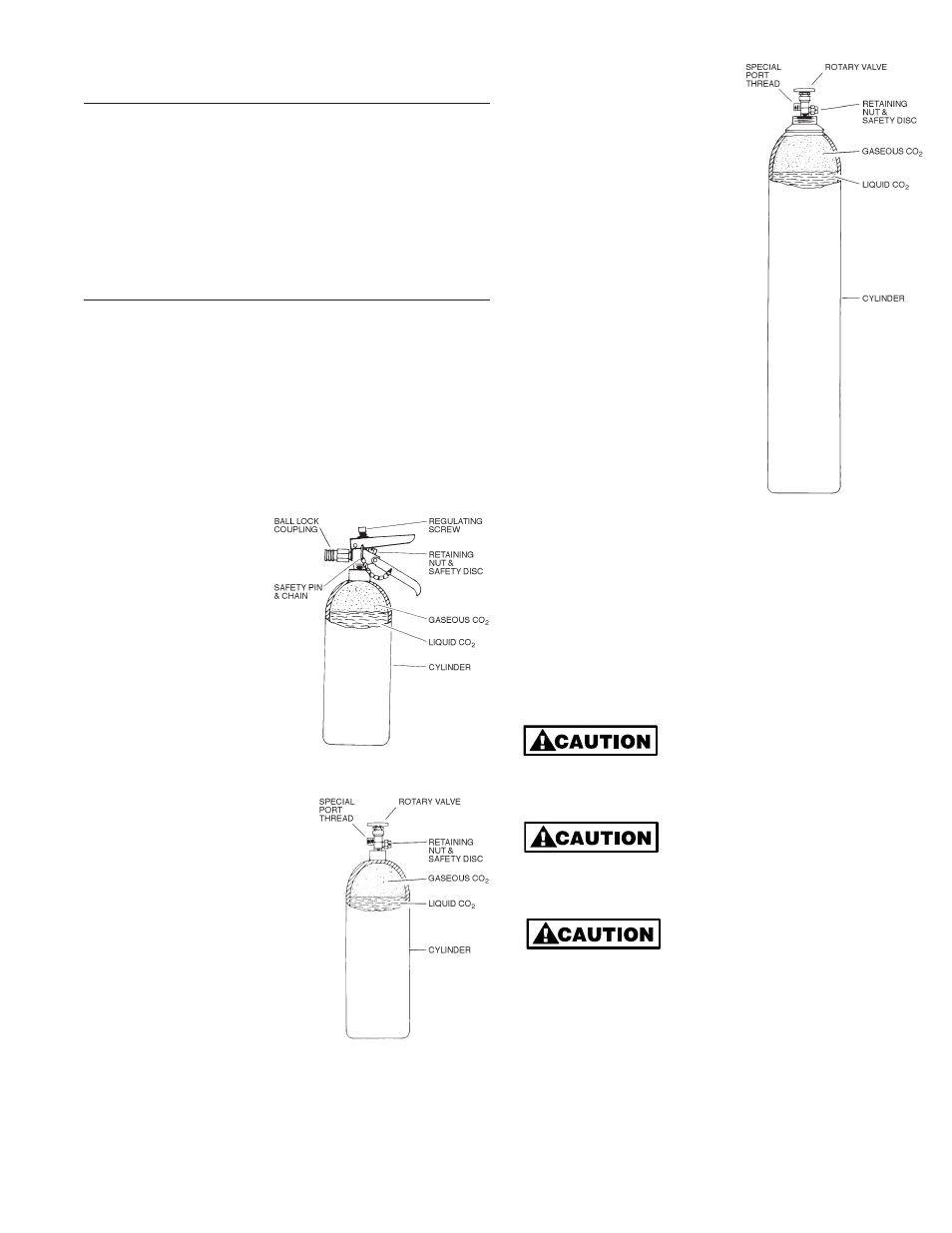
Model 950 50 Ib. CO2 Cylin-
der– The model 950, 50 Ib. CO
2
cylinder, is a cart transported
cylinder weighing approximately
154 Ibs. when fully charged with
50 Ibs. of liquid CO
2
(Refer to
Figures 3 and 9).
The cylinder is equipped with a
rotary hand valve with a special
port thread. The valve requires
a matching coupling nut and
stem with an O-ring face seal
as supplied on the Model 1105
CO
2
Operating Valve and Hose
Assembly.
A screw on valve safety cover is
supplied with the cylinder and
should always be in place when
the cylinder is not in use or while
the cylinder is being transported.
The 50 Ib. cylinder may be used
as a field refilling supply tank for
the 5 Ib. cylinder if desired. See
refilling instructions on page 6.
USE AND OPERATION
With the GB/Jet Line CO
2
system, gas generated from the liquid
CO
2
stored in the cylinder is used to propel the line carrier
and pull line through the conduit.
When using the CO
2
system, adjust the flow regulating screw on
the “squeeze to operate” valve handle on the 5 Ib. cylinder or on
the 1105 valve and hose assembly. Regulate the flow to a mod-
erate amount sufficient to keep the line carrier moving and the
line flowing into the conduit. Develop a light touch and conserve
CO
2
(Refer to Figure 4).
The valve handle is very easy to
operate when the regulating
screw is backed out. Do not
attempt to force the handle or damage to the screw and handle
could occur.
There is substantial force when
the valve is operated and CO
2
is
discharged in open air. Point the
nozzle in a safe direction and maintain a firm grip on the seal-off
frost guard and valve.
Where conduit is run under
ground; it may contain water or
be subjected to flooding. It may
be desirable to blow the water out before blowing a line in the
conduit. Because the water will be blown out ahead of the line
carrier, take precautions to protect nearby equipment that could
be damaged by moisture and sludge (Refer to Figure 16).
3
Figure 1
1103N 5 Lb. CO
2
Cylinder
Figure 2
1208 20 Lb. CO
2
Cylinder
Figure 3
950 50 Lb. CO
2
Cylinder