Gardner Bender CO2 CONDUIT FISHING SYSTEMS User Manual
Page 5
Connection to the 20 Ib. or 50 Ib. CO
2
cylinder rotary valve is
made with the special thread coupling nut and O-ring face seal
on the hose stem. The coupling nut screwed hand tight on the
valve port is all that is required for a good seal. When the cylinder
rotary valve is opened (opening one or two turns is sufficient) the
hose is pressurized up to the operator held hand valve.
Any of the GB/Jet Line CO
2
seal-offs may be threaded up with
pull line and line carrier and then connected to the operating
valve quick coupling. An adjusting screw is provided on the oper-
ating valve handle to limit the valve travel and regulate the flow of
CO
2
gas as required by the user.
When not in use, disconnect the seal-off from the operating
valve, close the cylinder rotary valve, operate the operating valve
to depressurize the hose and remove it from the cylinder valve.
Store the hose on the cylinder cart hose hanger hooks or in the
cart tool box.
Model 1142 Angle Adapter (See Figure 11) – The 1142 Angle
Adapter is provided for use with the 1215 seal-off for installing
line in small junction boxes and hard-to-get-to conduit.
To use, remove the rubber cone on the 1215 seal-off and screw
the angle adapter on the threaded end of the brass feed through
fitting.
Always maintain a firm grip on the seal-off hose behind the feed
through fitting to counteract the recoil force of the high velocity
CO
2
gas.
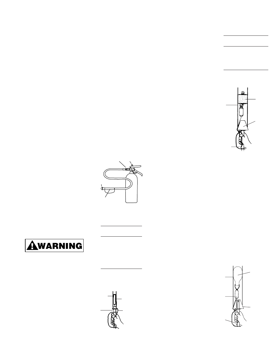
Blowing Line Packages through
Conduit – This is the easiest
method of placing a light weight pull
line in the conduit. The line package
or seal-off requires no thread up for
this operation. However, it is recom-
mended that the seal-off be connect-
ed to the operating valve and a pre-
liminary CO
2
flow adjustment be
made by alternately operating the
valve and adjusting the regulating
screw. If more CO
2
flow is required,
back out the regulating screw one
or two more turns (Refer to Figure 4
and 5).
Always maintain a firm grip on the
frost guard of the seal-off hose to
prevent it from whipping around.
Power Saver Line Package –
Select the Power Saver line pack-
age for size and length of line to fit
up to 1” diameter conduit. It is
recommended that you flex the
package back and forth two or
three times to loosen it prior to its
use. This will make the line easi-
er to dispense.
Proceed as follows:
1. Pull out approximately two
feet of line. Hold on to this trail-
ing end to prevent its loss in the
conduit.
2. Insert the line package in the conduit-foam tip first.
3. Hold the seal-off hose frost
guard, force rubber cone firmly in
the conduit entrance and give the
line package two or three quick
spurts of CO
2
. The package
should be blown through the con-
duit trailing a line as it goes
(Refer to Figure 6 and Table 1).
4. It is recommended that
the ends of the line be
tied off until ready for use
to prevent the end from
being accidentally pulled
back into the conduit.
Tag-Along Line Package -
Tag-Along Line Packages
perform the same function
as Power Saver line pack-
ages except they are used
in 1
1
/
4
” diameter and larger
conduit. Tag-Along pack-
ages must be used with a
line carrier to supply the
pulling force.
Select the Tag-Along Line
Package and a line carrier
either foam or inflatable that fits the conduit diameter and pro-
ceed as follows:
1. If a foam line carrier is selected, attach the Tag-Along pack-
age plastic eye to the foam line carrier hook. Pull out approxi-
mately two feet of line and hold on to the trailing end (Refer to
Figure 7).
2. Insert the foam line carrier and Tag-Along package in the
conduit.
3. Hold the seal-off hose frost guard, force rubber cone firmly in
the conduit entrance and squeeze the CO
2
operating valve
handle. Continue to apply a flow of CO
2
until line carrier
comes out the other end of the conduit. The run time will be
longer than for the Power Saver line package because of the
larger conduit and greater volume of CO
2
required. However,
the run time in 3” and 4” conduit 200 and 300 feet long should
be completed in a matter of seconds (Refer to Figure 7).
4. Tie off the ends of the
line to prevent it from
being accidentally
pulled into the conduit.
Inflatable Line Carrier
1. Select an Inflatable line
carrier within its conduit
diameter range and
attach the Tag-Along
Line Package to the
wire bail. Pull out
approximately two feet
of line and hold on to
the trailing end.
5
Figure 6
Blowing a Power Saver Line
Package In Conduit
Conduit
Length
Model
Dia.
Ft.
LP2150
1
/
2
”
150’
LP3200
3
/
4
”
200’
LP3300
3
/
4
”
300’
LP3450
3
/
4
”
450’
LP4200
1”
200’
LP4300
1”
300’
LP4450
1”
450’
Table 1
Power Saver Line Packages
CONDUIT
1215
SEAL-OFF
POWER SAVER
LINE PACKAGE
TRAILING END
OF LINE
Figure 7
Blowing a Foam Line Carrier and
Tag-Along in Conduit
FOAM
LINE
CARRIER
1216
SEAL-OFF
TRAILING
END OF LINE
CONDUIT
Length
Strength
Model
Ft.
Lbs.
LP2206T
400
22
LP2208T
600
22
LP2207T
800
22
LP1704T
1200
22
LP1705T
600
50
Table 2
Tag-Along Line Packages
Figure 8
Blowing an Inflatable Line Carrier and
Tag-Along in Conduit
THE
INFLATABLE®
LINE CARRIER
1216 SEAL-OFF
CONDUIT
TAG-A-LONG
LINE PACKAGE
TRAILING
END OF LINE
LOCK BALL
COUPLING
REG ULATING
SCREW
1215 SEAL-OFF
FROST GUARD
GRIP HERE
Figure 5
1103N Cylinder with 1215
Seal-Off Connected