Gardner Bender CO2 CONDUIT FISHING SYSTEMS User Manual
Page 4
BLOWING LINE IN THE CONDUIT
The GB/Jet Line CO
2
system is designed to blow a line in
“sealed” conduit such as EMT with compression type couplings,
rigid conduit, and plastic conduit with adhesive bonded joints.
These types of conduit generally require very little effort to install
a pull line with the CO
2
system.
There are some conduit runs that will be difficult or impossible to
blow a line in with the CO
2
system, such as:
• Conduit containing hard packed sand, silt, debris, or concrete.
• Conduit with separated joints.
• Conduit with two sizes of duct connected by a reducer coupling.
• Conduit with unsealed set screw couplings.
• Small diameter conduit of several hundred feet with multiple
bends.
PREPARATION
It is helpful to know the purpose for which a line is to be used
once it has been blown into the conduit. This will aid the user in
selecting the appropriate line for the job.
Knowing the approximate length of the conduit will prevent
selecting a line that is too short for the run; i.e., if the user wishes
to place a light line in a
3
/
4
” conduit with an estimated length of
195 to 200 feet, a 300 ft. power saver line package should be
selected for the run. An alternate solution would be to use a
3
/
4
”
foam line carrier pulling bulk nylon line. Either selection would
insure an adequate length of line.
Selecting the Pull Line – The following list is presented as a
guide in selecting a pull line. Users must determine for them-
selves which best fits their needs.
1. Identification of a conduit run termination where multiple con-
duit runs originate at a single location.
Recommended Line: Power Saver Line Packages or Bulk
Nylon Line.
2. Placing a line in the conduit for use at a later date.
Recommended Line: Small conduit
1
/
2
”,
3
/
4
”, and 1” Power
Saver Line Packages, Bulk Nylon Line or PL232. Larger con-
duit 1
1
/
4
” through 6” Tag-Along Line Packages, PL Series
Line PL232, PL235, and PL2310.
3. Pulling in a larger line, rope or steel winch cable.
Recommended Line: Small conduit
1
/
2
”,
3
/
4
” and 1”. Same as
2 above. Larger conduit PL232 or PL235.
4. Pulling wire in conduit.
Recommended Line: PL232, PL235, and PL2310.
SEAL-OFFS
Seal-offs provide a means of making the final connection
between the CO
2
operating valve and the conduit, as well as pro-
viding a means of feeding pull line into the conduit. The tapered
rubber cone that forms the seal at the conduit entrance must be
held firmly in the conduit when flushing out water and debris or
blowing line in the conduit. Be sure to keep a firm hold on the
seal-off hose frost guard while operating unit.
All CO
2
seal-offs are equipped with a male quick disconnect plug
that plugs into the operating valve ball lock coupling on the 5 Ib.
CO
2
cylinder valve or the 1105 operating valve and hose assem-
bly used with the 20 Ib. and 50 Ib. CO
2
cylinders (Refer to
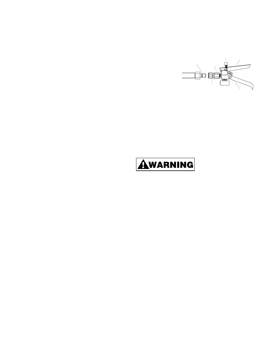
Figure 4).
Connect the seal-off to the 5 Ib. CO
2
cylinder valve or the 1105
operating valve as fol-
lows:
1. Rotate the valve ball
lock coupling sleeve
to align notch with
embedded ball
(Refer to Figure 4).
2. Retract the ball lock
sleeve.
3. Plug in seal-off connector.
4. Release the sleeve to lock coupling.
5. Rotate sleeve notch away from embedded ball to prevent acci-
dental disconnection.
Disconnect the seal-off from the CO
2
operating valve when
threading pull line through the feed port and attaching a line carri-
er. This step will make the preparation job easier and eliminate
the possibility of accidental discharge of CO
2
.
Always maintain a firm grip on
the seal-off hose frost guard
when the seal-off is connected
to the operating valve (See Figure 5). This will prevent the free
end from whipping around while discharging CO
2
.
Model 1215 Seal-Off – The 1215 Seal-Off with two foot hose is
designed for use with the 5 Ib. CO
2
cylinder for blowing line in
3
/
4
”,
1
/
2
”, 1”, and 1
1
/
4
” conduit. This seal-off is required for blowing
power saver line packages in
1
/
2
”,
3
/
4
”, and 1” conduit. The 1215
seal-off works equally well with the larger GB/Jet Line 20 and 50
Ib. systems when connected to the 1105 CO
2
operating valve
and hose assembly.
The feed through port will accept bulk nylon line and pull line up
to
1
/
8
” diameter.
Model 1216 Seal-Off – The 1216 Seal-Off with two foot hose is
similar to the 1215 except for a larger sealing cone. It may be
used in conduit sizes 1
1
/
2
” through 2
1
/
2
” diameter and with pull
line up to
1
/
8
” diameter.
Model 1206 Seal-Off – The 1206 Seal-Off is designed for use
with the larger GB/Jet Line 20 and 50 Ib. CO
2
systems. It must be
used with the 1105 operating valve and hose assembly. The
large rubber cone will fit conduit sizes 1
1
/
2
” through 6”. The feed
through port will accept all GB/Jet Line PL Series pull lines
PL232, PL235, and PL2310.
OPERATING ACCESSORIES
GB/Jet Line provides specially designed easy-to-use operating
accessories for the CO
2
systems that meet most conduit fishing
needs.
Model 1105 Operating Valve and Hose Assembly – The 1105
operating valve and 12 ft. hose assembly connects to the 20 or
50 Ib. CO
2
cylinder and allows the operator a wide range of
movement to reach hard-to-get-to conduit runs.
4
RETAINING NUT
& SAFETY DISC
OPERATING
HANDLE
REGULATING SCREW
BALL LOCK
COUPLING
SEAL-OFF FITTING
MALE PLUG
SLEEVE NOTCH &
EMBEDDED BALL
CARRY HANDLE
Figure 4
Operating Valve and Seal-Off Coupling