Gardner Bender B2000 Series G Cyclone Bender User Manual
Page 4
3.
Check the bending shoe to be sure the correct grooves for
the conduit being bent are facing toward the operator. If
the shoe must be rotated, hold the pendant control toggle
switch in “Return” and press the jog button until the zero
light goes out. The shoe will rotate 180° then stop in the
load position. See Figure 7.
Figure 7. Pendant Control
4.
When bending 1
1
⁄
4
" - 2" conduit, position roller housing
and upper arm. Then push the conduit between the shoe
groove and the 2" nylon rollers until the bend mark on the
conduit is in line with the outside edge of the clamp jaw.
5.
Grasp the upper urethane roller and move the support
arm counterclockwise until it contacts the roller housing.
The two nylon rollers should have moved against the
conduit and should firmly hold the conduit in the shoe.
See Figure 8.
Figure 8. Locking in Roller Support
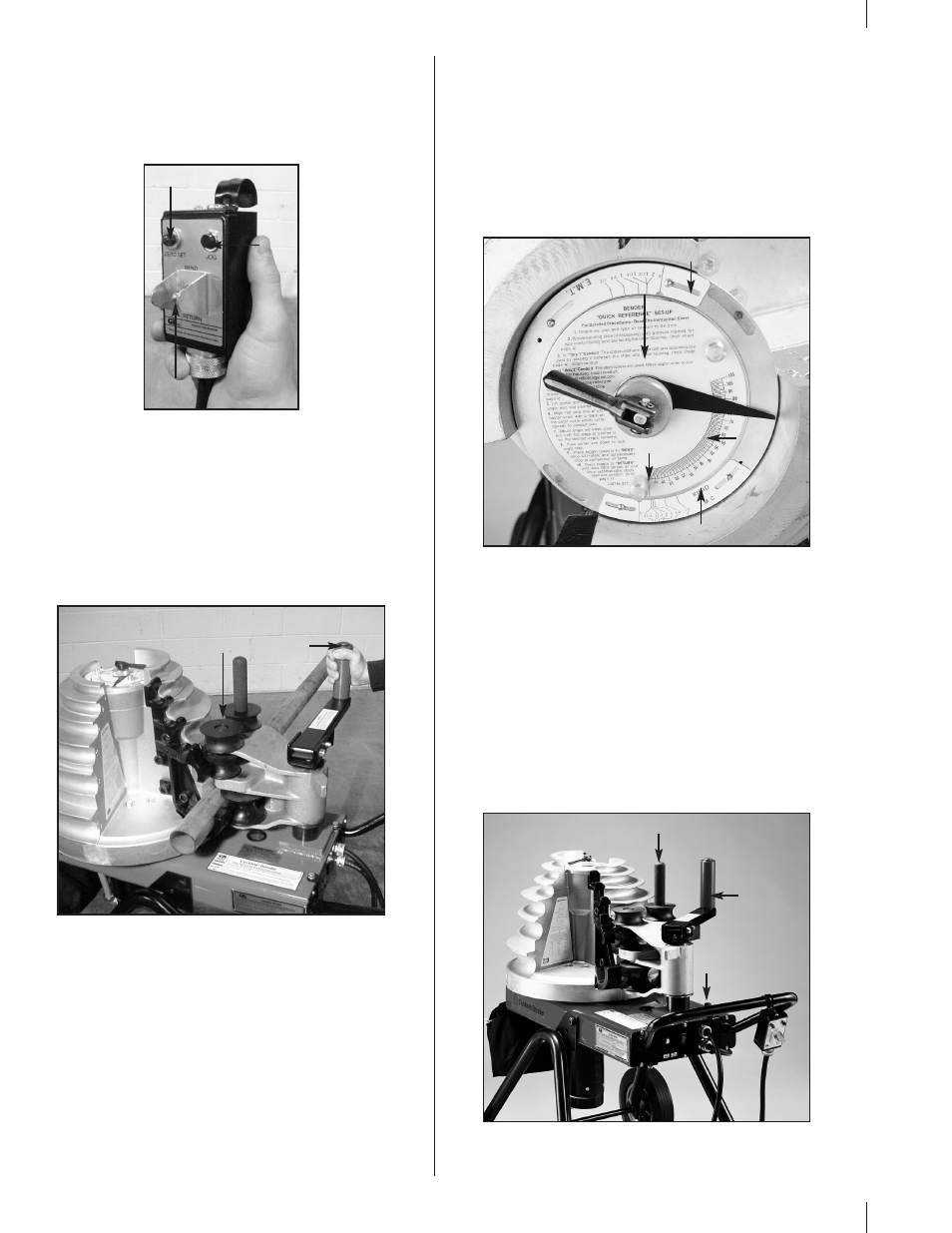
6.
Each time a different size and type of conduit is being
bent, three facts must be determined and set into the
bender shoe control system. The required settings are:
conduit size, material and desired bend angle. Prior
to setting, be sure the pipe size scale is toward the
operator and the correct shoe grooves are also toward
the operator.
a.
Lift the locking handle to release the angle set knob
and angle disc. Use the two small pins to rotate the
angle disc, clockwise. See Figure 9.
b.
Set the bender for specific conduit size by turning the
angle disc until the red line and pointer are on an
outer size scale mark which matches the size conduit
being bent. See Figure 9. Be sure the correct size
scale is being used (EMT, lMC, or Rigid).
c.
Move the angle set knob (See Figure 9) until the flat
edge of the pointer is on the line indicating the exact
degree of bend desired. Lower the center arm to lock
the pointer, angle disc and to prevent inadvertent
movement during bending.
Figure 9. Set Angle Indicator
7.
Use the control pendant. The zero light should be on. Hold
the toggle switch in the “Bend” position. The shoe will
rotate until the desired bend is achieved, then
stop automatically.
NOTE: If the zero light is not on, press the toggle switch to
return until the shoe stops and the zero light comes on.
8.
To unload conduit, hold the toggle switch in the “Return”
position. The shoe will return to the start position and
stop automatically.
9.
Grasp the upper urethane roller and move the support
arm clockwise until the rollers move away from the
conduit. See Figure 10. Push the roller housing against
the frame stop. Remove bent conduit.
Figure 10. Unload Conduit
4
Zero Light
Toggle
Switch
Jog
Button
Upper
Urethane
Roller
Nylon
Rollers
Zero Point
Rigid/IMC Size Scale
Angle Disc
Angle Set Knob
EMT Size Scale
Frame Stop
Upper
Urethane
Roller
Roller Housing Handle