Fluid Components International ST75_ST75V User Manual
Page 15
ST75/ST75V MASS FLOW
FLUID COMPONENTS INTERNATIONAL LLC
This page is subject to proprietary rights statement on last page
15
Doc. No. 06EN003368 Rev. C
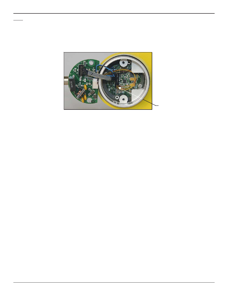
Step 3
Verify sensor element continuity and resistance.
Remove sensor element cable from the bottom of the control circuit assembly. Note that 2 of the wires have a red stripe and are
located closest to the interconnecting cable header. Using an ohm meter verify that resistance between the 2 red striped wires is
approximately 1100 ohms +/- 20. This resistance is temperature dependant. The resistance at 70 degrees F should be 1082 ohms.
Verify the resistance between the 2 natural colored wires are approximately the same.
FCI provides full in-house technical support. Additional technical representation is also provided by FCI field representatives. Before
contacting a field or in-house representative, please perform the troubleshooting techniques outlined in this document. If problems
persist, contact the FCI Customer Service department at 1-800-854-1993 or 1-760-744-6950.
If the instrument is to be returned to FCI, please obtain an Return Authorization. The form contains a declaration of decontamination
cleaning information that the instrument must comply with before it is shipped to FCI.
Sensor Element Cable