Alert – Fluid Components International GF92 User Manual
Page 4
Model GF92 Flowmeter
4
Doc. No. 06EN003321 Rev.-
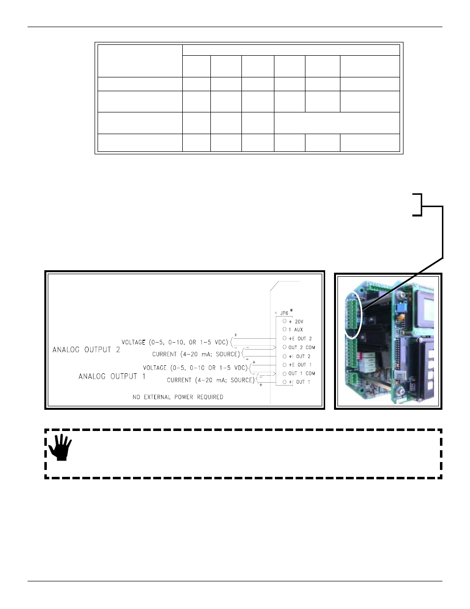
Analog Output 2 is connected in a similar manor as Analog Output 1. ( For Voltage Output: 0 - 5, 0 - 10 or 1 -5 Vdc;
connect a positive wire to + E OUT2 and a negative wire to OUT 2 COM. For Current Output: 4 - 20 mA; connect a
positive wire to + I OUT2 and a negative wire to OUT 2 COM.) See GF Series manual 06EN003229 for details.
Wire Gauge Versus Distance Of Wire To Run
For Voltage Output: 0 - 5, 0 - 10 or 1 -5 Vdc; connect a positive wire to + E OUT and a negative wire to OUT COM.
Analog Output Plug Location
Wiring the Instrument’s Signal Output to the Customer Application:
Alert:
Either voltage or current from the Analog Outputs can be connected to the customer application, not both.
(Example: Voltage and current from analog output 1 cannot be connected.) However, one Analog Output
can be wired for current and the other Analog Output can be wired for Voltage.
Customer Connections, Analog Output Diagram
For Current Output: 4 - 20 mA; connect a positive wire to + I OUT and a negative wire to OUT COM.
Connection
Maximum Distance for AWG
10 ft.
(3m)
50 ft.
(15m)
100 ft.
(31m)
250 ft.
(76m)
500 ft.
152m)
1000 ft.
(305m)
AC Power
22
22
22
20
18
16
Relay (2A, at
220VAC)
24
22
20
16
12
Not
Recommended
Relay (10A, at
120VAC or 24VDC)
22
16
12
Not Recommended
Flow Element Wires
for Remote Option*
24
24
24
22
22
18
INSTALLATION, OPERATION AND TROUBLESHOOTING GUIDE
FLUID COMPONENTS INTL