Fluid Components International FR73B Manual Troubleshooting User Manual
Page 2
FLUID COMPONENTS INTL
CHAPTER 5 - TROUBLESHOOTING
Model FR78B Flow Switch/Monitor
5 - 2
Doc. No. 06EN003281 Rev. -
Check Application Design Requirements
Application design problems can occur when instruments are first installed into the process media. The
application design should also be checked on instruments that have been in operation for some time. If the
application design does not match field conditions, errors occur.
1.
Review the application design with plant operation personnel and plant engineers.
2.
Ensure that plant equipment such as pressure and temperature instruments conform to the actual conditions.
3.
Verify operating temperature, operating pressure, line size, and gas medium.
Control Circuit Dash Number Specification
Verify that wiring is connected per the wiring diagram in Appendix A.
Verification of Flow Element Resistance
The measurements are based on a standard (4K ohm RTD at 70°F, or 21°C) flow element. Variation of
±
100
ohms from nominal is to be expected, depending on temperature. The maximum allowable difference in resistance
between matched RTD's is 1% at ambient temperature (immersed in water). The heater resistance should be
221
±5
ohms.
1.
Turn off the operating power to the instrument.
2.
Gently remove (pull straight out) the control circuit from the socket. Using a DMM, measure the resistance of
the active and reference RTD sensing elements.
Note:
The resistance of the active RTD will be greater than the resistance of the reference RTD whenever
the heater is on.
3.
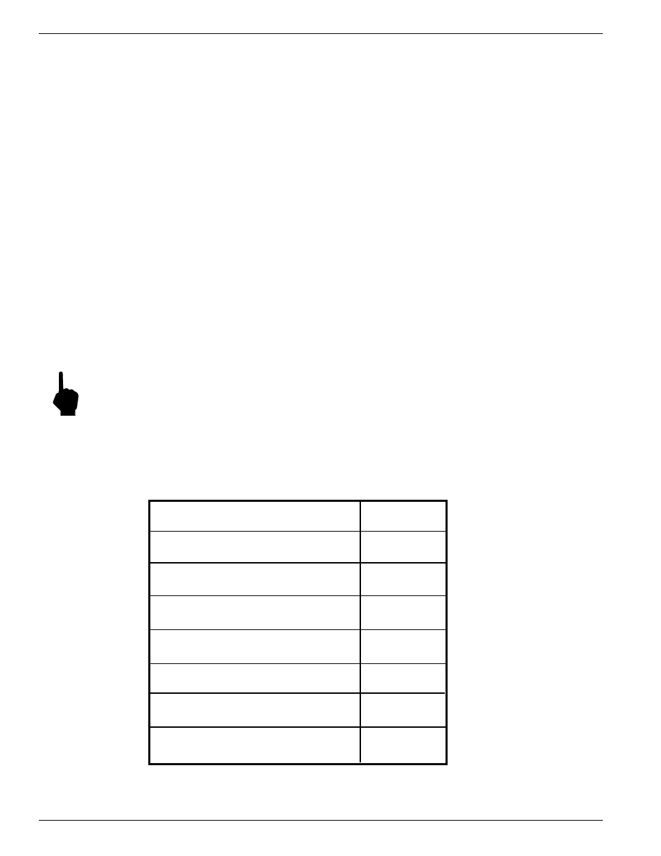
Measure the resistances as found in Table 5-1 to determine if the flow element is functional. The resistance is
dependent on a temperature of 70°F (21°C)
Table 5-1. Flow Element Resistances In Ohms
Terminal Pin Number
Resistance
(Wire Color)
In Ohms
From Pin 7 (White, Black and Shield)
4000
To Pin 8 (Yellow)
From Pin 8 (Yellow)
4000
To Pin 9 (Red)
From Pin 7 (White, Black and Shield)
221
To Pin 10 (Blue)
From Pin 7 (White, Black and Shield)
8000
To Pin 9 (Red)
From Pin 8 (Yellow)
4221
To Pin 10 (Blue)
From Pin 9 (Red)
8221
To Pin 10 (Blue)
Shield To All Pins
Open
Circuit