Sensing element installation, Control circuit installation, Wiring installation – Fluid Components International 8-66B_12-64B Series Manual Installation User Manual
Page 2
FLUID COMPONENTS INTL
CHAPTER 2 - INSTALLATION
Models 12-64/8-66 Basic Switch
2 - 2
Doc. No. 06EN003264 Rev. A
The above precautions are minimum requirements to be used. The complete use of ESD precautions can be found in
the U.S. Department of Defense Handbook 263.
Verify Installation Location
Prepare the vessel for installation, or inspect the already prepared location to ensure that the instrument will fit into
the system. Prepare the necessary sealants or gaskets to provide a leakproof installation for the application if
required. The location of the 12-64 that should have been prepared at the time of order should be at least 20 pipe
diameters downstream and 10 pipe diameters upstream from any bends or interference in the process pipe or duct to
achieve the greatest accuracy.
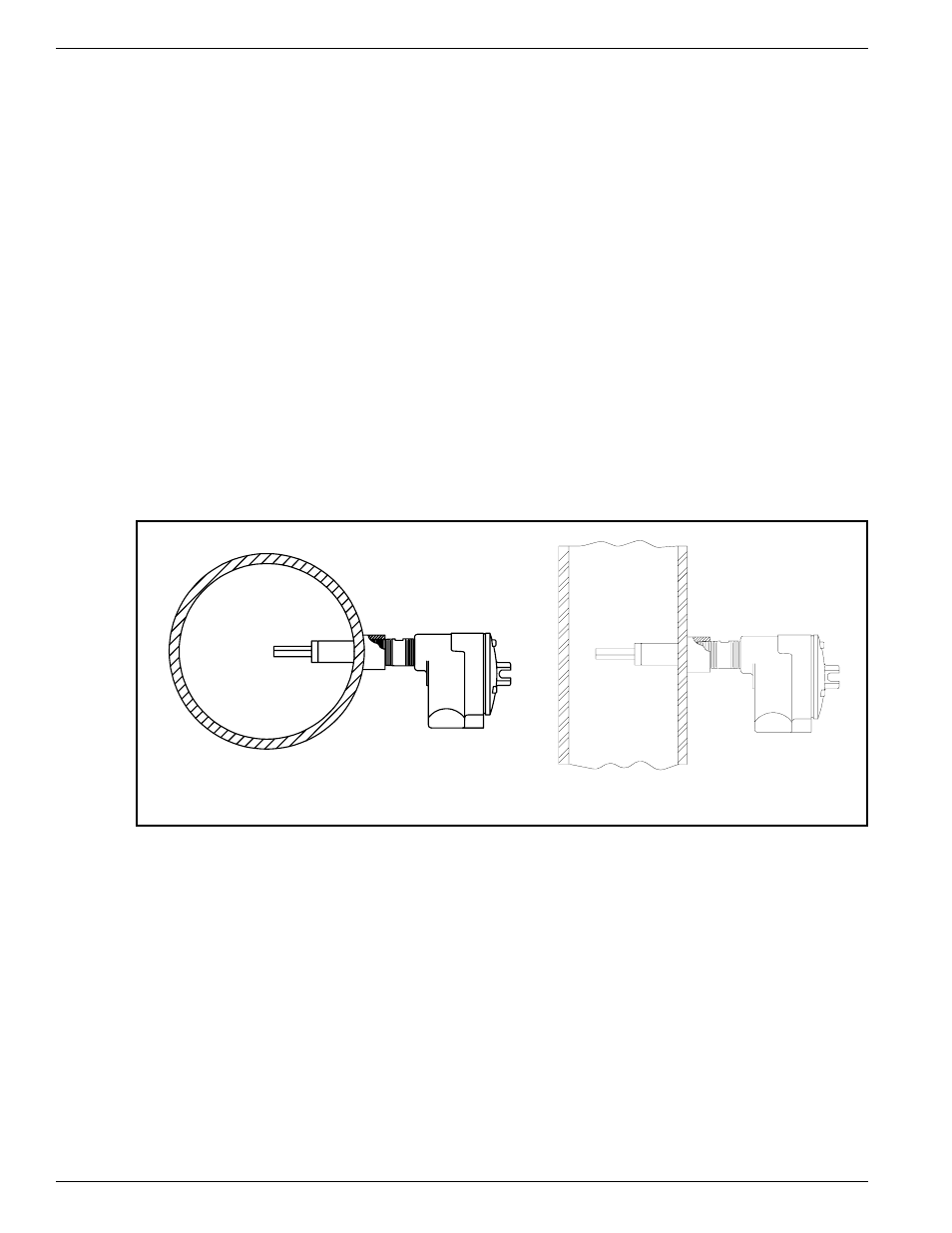
Sensing Element Installation
Install the sensing element in the process piping at the desired location. Verify that the flat area machined into the
sensing element is flat and level. If the flat is present it is machined on the sensing element near where it is screwed
into the enclosure. "FLAT UP & LEVEL" is also etched on the flat surface.
Apply a lubricant/sealant compatible with the process to all threads. Use a pipe wrench for 1-1/4 inch (32 mm) NPT
and larger connections, or an open-end wrench for 1-1/4 inch (32mm) NPT and smaller connections. All
connections should be tightened firmly. To avoid leaks, do not overtighten or cross-thread connections. The figures
in Appendix A and Figure 2-1, show this configuration.
If the sensing element is mounted in a downward direction, moisture build up in the enclosure needs to be avoided.
FCI recommends that an O-ring be used on the enclosure cover. In addition, attached conduits must be isolated by
using a conduit potting Y.
Figure 2-1. Sensing Element Threaded Mounting
Control Circuit Installation
The configuration of the instrument is with the control circuit already installed in the local enclosure (the control
circuit is physically mounted with the sensing element).
Wiring Installation
Conduit Routing
All socket and/or terminal block connections are to be made through the 1 inch female NPT openings in the
enclosure. FCI strongly recommends that all electrical cables be run through an appropriate conduit for the
protection of the instrument and personnel.
Protection of the control circuit from moisture is an important consideration. Keep the entry of the conduit into the
12-64 BASIC
8-66 BASIC
C00166-1
C00033-1