Burkert Type 8112 User Manual
Page 14
Keep in mind that this welded socket is not suitable for coated
instrument versions.
Screw LEVEL SWITCH 8112 completely into the welded socket. The
later position can be determined already before welding. Mark the
appropriate position of the welded socket. Before welding, unscrew
LEVEL SWITCH
8112 and remove the rubber ring from the welded
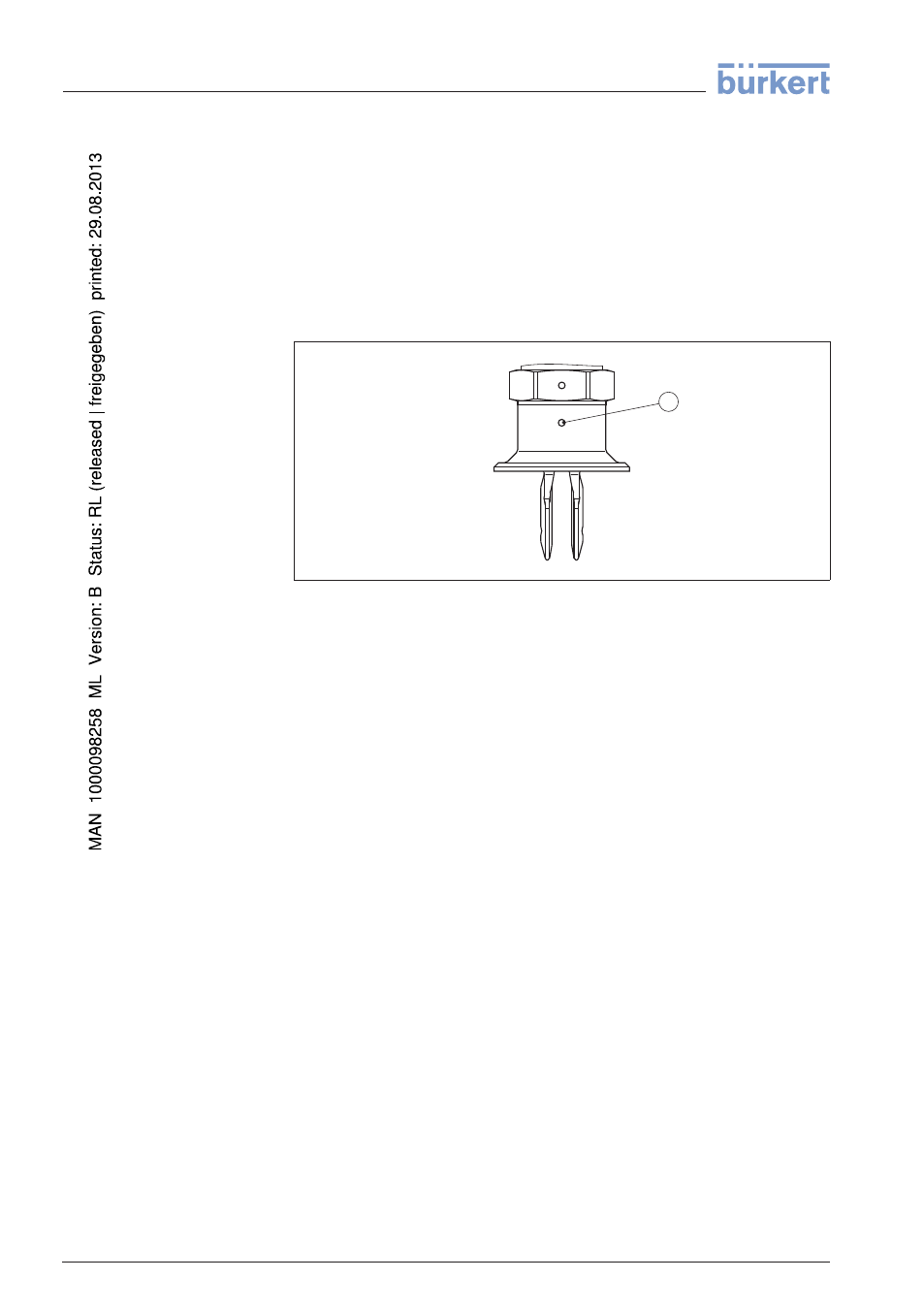
socket. The welded socket has a marking (notch). Weld the socket
with the notch facing upward, or in case of pipelines (DN 32 up to
DN
50), aligned with the direction of flow.
1
Fig. 7: Marking on the welded socket
1
Marking
In case of horizontal mounting in adhesive and viscous products, the
surfaces of the tuning fork should be vertical in order to reduce buildup
on the tuning fork. On the screwed version you will find a marking on
the hexagon. With this, you can check the position of the tuning fork
when screwing it in. When the hexagon touches the seal, the thread
can still be turned by approx. half a turn. This is sufficient to reach the
recommended installation position.
With flange versions, the fork is directed to the flange holes.
When used in adhesive and viscous products, the tuning fork should
protrude into the vessel to avoid buildup. For that reason, sockets for
flanges and mounting bosses should be avoided when mounting
horizontally.
If LEVEL SWITCH 8112 is mounted in the filling stream, unwanted
false measurement signals can be generated. For this reason, mount
LEVEL SWITCH
8112 at a position in the vessel where no
disturbances, e.g. from filling openings, agitators, etc., can occur.
This applies particularly to instrument types with long extension tube.
Adhesive products
Inflowing medium
14
LEVEL SWITCH
8112 • with NAMUR output
4 Mounting
32052
-EN
-120418