Type 8660 control center – Burkert Type 8660 User Manual
Page 8
Type 8660 Control Center
________________________________________________________
- 8 -
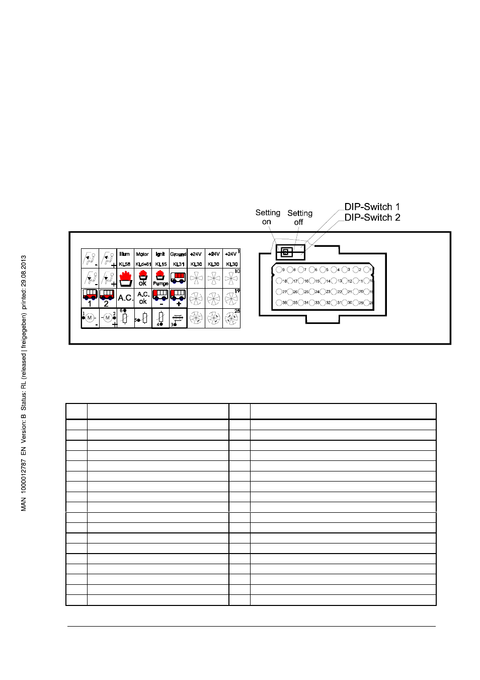
Plug wiring diagram for Control Center 2 and 3
Figure 3 shows the backside of Control Center 2 and 3 with the plug (right) and the
symbol list for the pins (left). The plug holds pins 1 to 36. The symbols for the
individual pins correspond fully with the symbols on the operating elements (see
Figure 7 and Figure 8). For further clarification, the plug wiring diagram is described
again in words in Figure 4.
Figure 3: Backside of Control Center 2 and 3 (Cannon/ITT plug)
Pin
Connection
Pin
Connection
1 24 V
19 front box blower level 2
2 24 V
20 front box blower level 2
3 24 V
21 front box blower level 2
4 ground
22 fresh air / circulation air flap +
5 ignition on (terminal 15)
23 fresh air / circulation air flap -
6 motor on (terminal d+61)
24 feedback Cooling unit on (only with CC 3)
7 illumination (terminal 58)
25 cooling unit (only with CC 3)
8 front box flaps windshield
26 passenger area floor unit level 2
9 front box flaps windshield
27 passenger area floor unit level 1
10 front box blower level 1
28 front box blower level 3
11 front box blower level 1
29 front box blower level 3
12 front box blower level 1
30 front box blower level 3
13 passenger area roof unit
31 valve potentiometer, shield
14 supplementary water pump
32 valve potentiometer, ground
15 feedback Supplementary heater on
33 valve potentiometer, sliding contact
16 supplementary heater
34 valve potentiometer, supply +
17 front box flaps floor area
35 front box valve motor
18 front box flaps floor area
36 front box valve motor