Burkert Type 8605 User Manual
Page 5
16
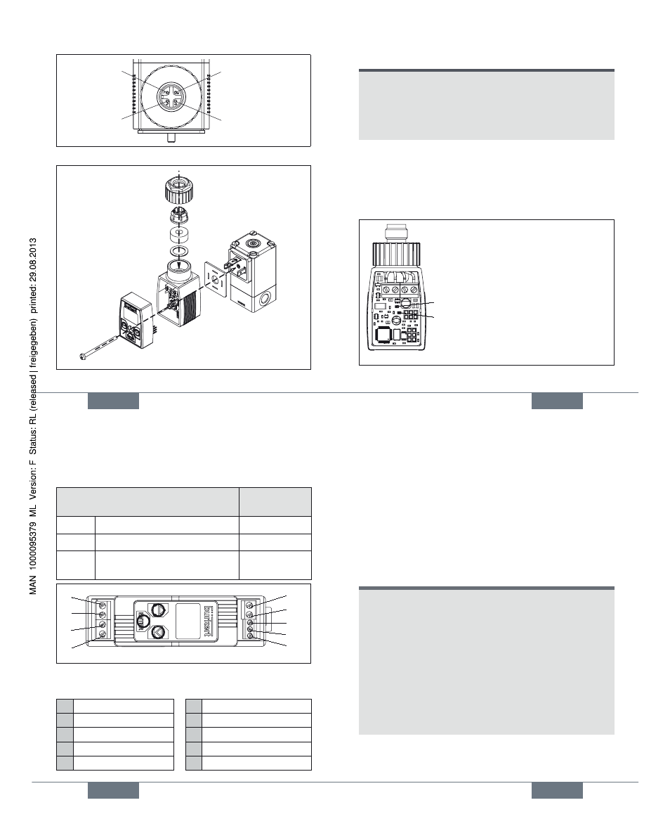
�tandard signal (+)
�tandard signal (�)
12 ... 24 V DC
GND
Fig. 4: Plug connector connection
Tighten screw M3 to max. 0.3 Nm
Fig. 5: Assembly at the valve
english
17
NOTE!
Ensure proper seating of the valve when screwing onto
the valve (cable plug version).
Do not tighten the screw M3 too tightly (max. 0.3 Nm),
as otherwise the housing will be deformed and proper
operation of the keys will no longer be possible.
8.2.2. LEDs during operation without
operating unit
During operation of the control electronics Type 8605 cable
plug version without operating unit, the operating status is
indicated by two LEDs.
LED green: Device in operation
LED yellow: Current through valve
Fig. 6: LEDs for version without operating unit
english
18
8.2.3. Type 8605 DIN rail version
The electrical connection of Type 8605 DIN rail version is
made via terminal strips.
Terminal strip
Cable
cross-section
2�pin
For valve
max. 1.5 mm
2
3�pin
For R�232 or R�485 interface
max. 0.5 mm
2
4�pin
For voltage supply and
standard signal
max. 1.5 mm
2
1
2
5
6
3
4
7
8
9
Fig. 7: Terminal strip connection
Legend to figure:
1 12 ... 24 V DC
6 Valve
2 GND
7 R�485�B / TxD
3 �tandard signal (�)
8 R�485�A / RxD
4 �tandard signal (+)
9 GND
5 Valve
english
19
9. CLEANING
Use the normal cleaning agents to clean the Control Elec�
tronics, Type 8605. Use no alkaline cleansing agents, as these
have a damaging effect on the materials used.
10. PACKAGING, TRANSPORT,
STORAGE
NOTE!
Transport damages!
Inadequately protected equipment may be damaged
during transport.
• During transportation protect the device against wet
and dirt in shock�resistant packaging.
• Avoid exceeding or dropping below the allowable
storage temperature.
Incorrect storage may damage the device.
• �tore the device in a dry and dust�free location!
• �torage temperature. �40 …+ 55 °C.
english
Type 8605