English, Pneumatic installation, Installation of the valve – Burkert Type 2700 User Manual
Page 10
8 - 2700
C
OMMISSIONING
english
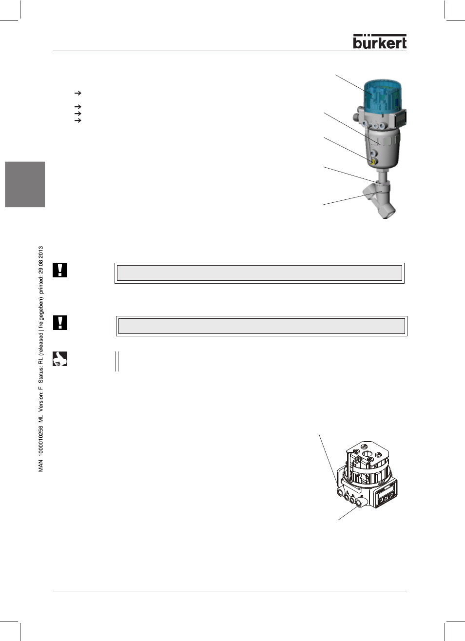
The control valve is driven by compressed air via the Top
Control.
Control medium:
instrument air,
Class 3 to DIN ISO 8573-1
£
£
£
£
£
Remove the protective caps from the ports.
➔
➔
➔
➔
➔
Apply the supply pressure to port ”1”.
The supply pressure necessary for complete opening or closing of the valve
may lie between the minimum values of 3 and 6 bar, depending on the
actuator. The permissible maximum value for the control pressure is 7 bar. The
values for the pressure supply are given under p
Pilot
on the rating plate of each
control valve.
➔
➔
➔
➔
➔
Attach the exhaust line or silencer to port ”3”.
Pneumatic installation
May be installed in any position, but preferably with the drive unit above.
Observe the flow direction - general rule for control valves: flow input under
seat!
Clean the piping of contamination!
Before connecting the valve housing, take care that piping is aligned!
In the case of weld-on housings, be sure to remove the drive unit before
welding.
Procedure:
1. Remove the electrical and pneumatic supplies from the Top
Control.
2. Pull off the pneumatic hose between Top
Control and drive unit at control
connection of drive unit.
Installation of the valve
3. Control function A: Pressurize the lowr port of the actuator with
compressed air (6 bar), so that the control cone is lifted from the valve
seat and is not damaged.
Control function B: With control function B, no compressed air must be
applied for this purpose.
4. Remove the actuator in the open valve position by unscrewing the nipple
from the housing.
5. Before reinstalling the actuator (in the open valve position), grease the
nipple thread with stainless steel lubricant, e. g. Klüberpaste UH1 96-402
from Messrs. Klüber.
6. Replace the graphite seal.
7. After tightening the threaded nipple, align the control ports by turning the actuator.
ATTENTION!
The valve must be for this in the opened position
.
NOTE
When using in an aggressive environment, you are advised to connect pneumatic hoses to all free control
connections and place their other ends in a neutral atmosphere.
Fluidic connections of the
TopControl Continuous
Outlet air connector
(inscription: 3)
Supply pressure connector
(inscription: 1)
threaded
nipple
Top
Control
actuator
housing
lower
control port
ATTENTION!
For special applications such as for oxygen and analysis, use only the approved lubricants.