Brooks Instrument SLA7810/20 User Manual
Page 21
2-5
Section 2 Installation
Installation and Operation Manual
X-PR-SLA7800-PC-eng
Part Number: 541B047AAG
December, 2008
Model SLA7810 & SLA7820
Voltage Output
+
+
+
1
15
9
8
Power Supply
15 Vdc
Voltage
Setpoint
Input
Signal Output
Common
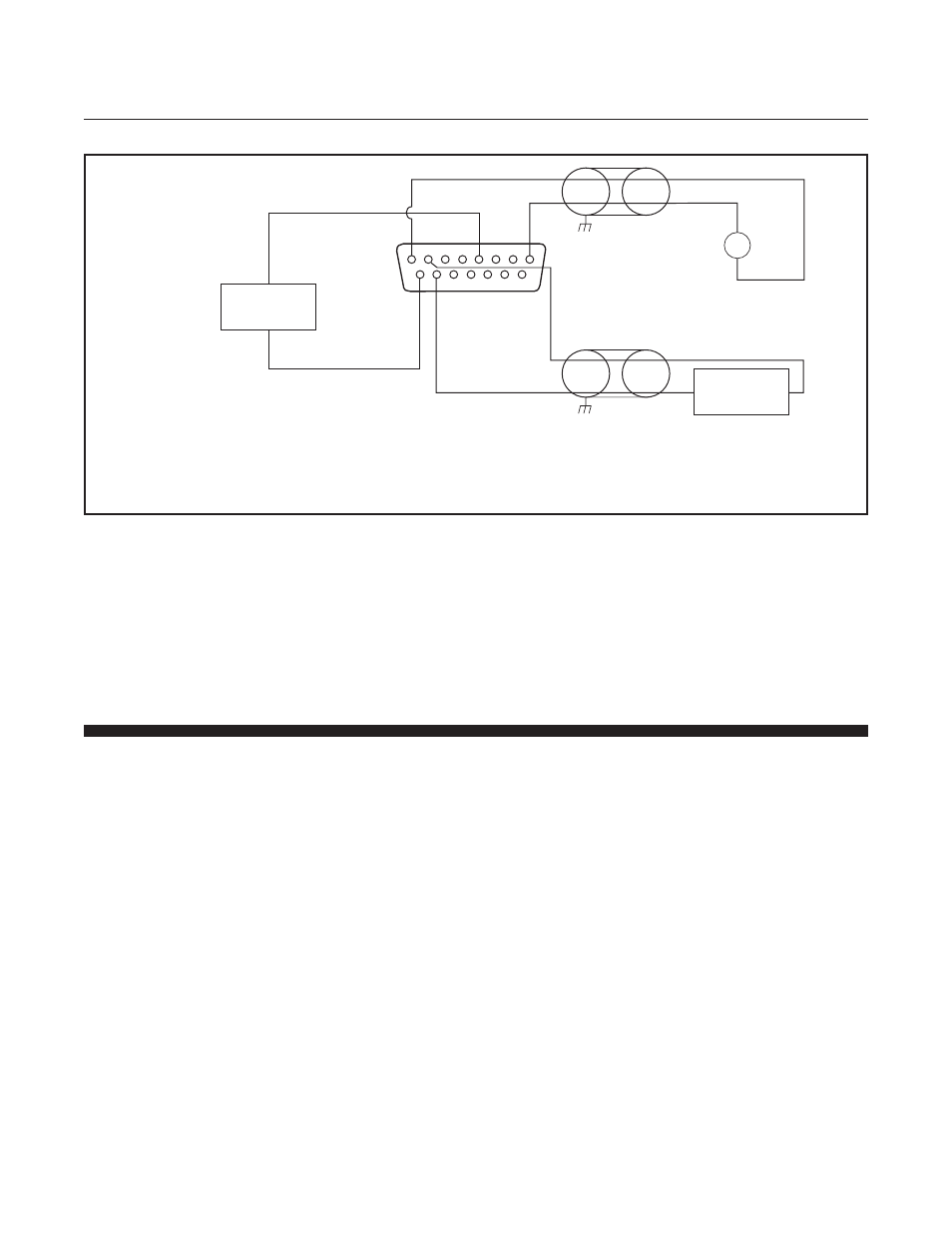
Voltage Signal: Setpoint and Output
Com
Note
Indicator or
Receiver
V
Notes:
1. The commons for the setpoint input and signal output are not isolated from power supply common.
2. Tie cable shields should connect to ground at one end only.
Figure 2-1 Common Electrical Connections, Analog I/O
Electrical Interface DeviceNet Mode
Electrical Interface in DeviceNet mode is covered in the DeviceNet
TM
Supplemental Instruction Manual for Brooks Models SLA7810 and
SLA7820
(X-DeviceNet-PC-eng)
2-11 Remote Setpoint (Command) Input Analog Mode
If the pressure controller will be commanded by an external voltage or
current signal, the command potentiometer is not used.
The command hookup is as follows:
a. Voltage Signal: Connect the external setpoint signal to Terminal 8 and
the external setpoint return to Terminal 1. Refer to Figure 2-1.
b. Note: The setpoint return is internally connected to signal return and
power supply common. Current supplied by the device providing the set
point will not be returned on the current loop.