D. chain installation (continued) – FlexLink Конвейерная цепь Монтаж User Manual
Page 2
470
D. Chain installation
D. Chain installation (continued)
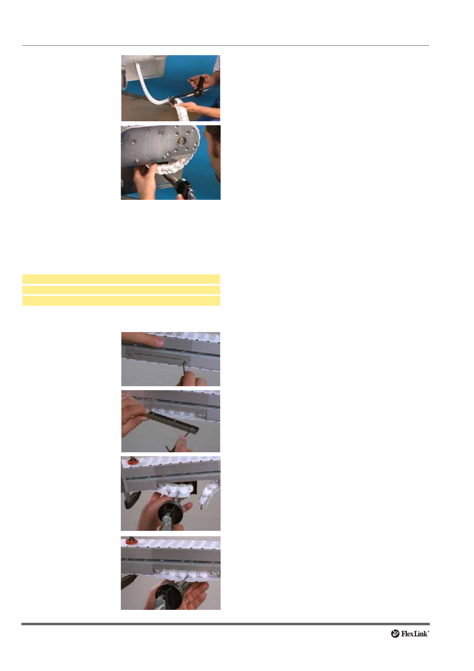
Using a beam section for chain installation
The beam section X_CC 160/XKCC 200 is used to per-
mit chain installation anywhere along the conveyor.
Tools required
Procedure
Length adjustment of the conveyor chain
End drive, intermediate drive and catenary drive units
1 Adjustment of the conveyor chain is carried out at the
drive end of the conveyor.
2 Remove catenary protection plates to allow easy
access for the pin insertion tool.
3 The conveyor chain should be tensioned within the
conveyor system by pulling down the conveyor chain
at the chain catenary in the underside of the drive unit.
Clamp across the conveyor chain to trap the chain on
to the beam profile. The clamp should be placed over
the edges of the drive unit to reduce the risk of dam-
age to the aluminium profile.
4 Remove all slack links from the conveyor chain using
the pin insertion tool.
5 Rejoin the conveyor chain.
6 Remove the chain clamp and reinstall the catenary
protection plates. The conveyor is now ready for oper-
ation.
Horizontal bend drive units
In a wheel bend drive, the outer aluminium profile can be
removed by slackening the set screws in the beam con-
necting strips. The slide rail must be fitted to allow the
removal of this section. A slide rail fastened with rivets
must not be longer than the outer bend section.
1 After removal of the outer aluminium profile, the con-
veyor chain can be pulled out of the wheel bend disc.
Lift the chain upwards.
2 Remove chain links using the pin insertion tool.
3 Rejoin the chain ends.
4 The tensioned chain can now be pulled back into
position on the bend guide disc, and the outer profile
put into place.
Guided drive units
Drive unit types X_EB HLG/HRG, X_EB HLGP/HRGP.
1 Adjustment of the conveyor chain is carried out at the
idler end unit.
2 Undo the screws on one side plate and remove it.
3 Undo the screw holding the shaft. Remove the idler
wheel together with the shaft.
4 Remove the required number of links.
5 Reinstall the idler wheel and shaft together with the
chain. Tighten the screw that holds the shaft.
6 Reinstall the side plates, make sure that the slide rails
are properly installed. Tighten the screws.
3 Join 5 meter lengths of
chain when necessary.
4 Remove links if neces-
sary, so that the chain
will exhibit some slack
at the drive unit. Length
adjustment, see
page 470.
Join the chain ends.
See page 469.
Allen key
Pin insertion tool
X..MJ
Clamp
1 Loosen the screws on
the beam section
flanges
2 Remove the flange so
that the chain becomes
accessible.
3 Clamp the chain to the
beam profile. Use the
chain tool to remove a
steel pin from the chain,
so that two links are
separated.
4 Remove excess links
and use the chain tool to
join the chain ends.