Top view of pipe – Dynasonics DDFXD Doppler Ultrasonic Flow Meter User Manual
Page 8
8
06-DPP-UM-00147 02/12
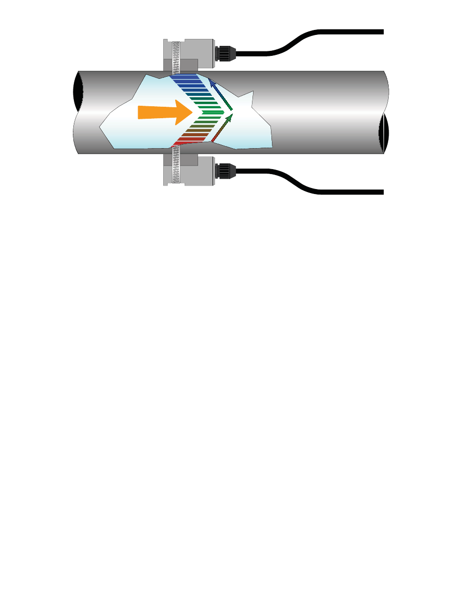
FLOW
Top View
of Pipe
FIGURE 1.2 - TRANSDUCER DIRECTION
3 - TRANSDUCER CONNECTIONS
1) Mount DFX monitor within the length of the transducer cables. While transducer cable extension
is not generally recommended, if additional transducer cable length is required, utilize cable and
connectors of the correct type and impedance. In many cases, especially if a splice my be exposed
to water or other liquids, it may be more effective to replace the entire cable. Transducers use
RG59 ,75 ohm coaxial cable or Twinax (Belden #9463) or (Belden # 9463DB) 78 Ohm two conduc-
tor cable.
2) Route the transducer cables through the center conduit hole in the bottom of the DFX enclosure
and connect to terminal block J4. The terminal blocks are a removable and can be disconnected
to simplify wiring access. A wiring diagram is located on the inner door for reference.
4 - STARTUP
INITIAL SETTINGS AND POWER UP
1) Verify that the DFX power supply jumper settings are properly configured for the power supply
that will be utilized. A wiring and jumper selection diagram is located on the inner door for refer-
ence.
NOTE: Power supply selection is specified during order placement and appropriate jumpers are placed at the factory. If power is
changed from AC to DC or vice versa, the fuse requirement will change. Fuse ratings are listed on the transmitter’s door.
2) Route power connections through the conduit hole farthest to the left and in the DFX enclosure.
Then connect power to the J2 terminal block. See Figure 3.2.
3) Apply power.
4) On initial power-up, the DFX conducts a series of self-diagnostic tests and buffering operations
that take approximately 30 seconds.
5) Enter pipe internal diameter (Pipe ID), measuring units and output configuration.