Flow direction arrow – Dynasonics DDFXD Doppler Ultrasonic Flow Meter User Manual
Page 21
06-DPP-UM-00147 02/12
21
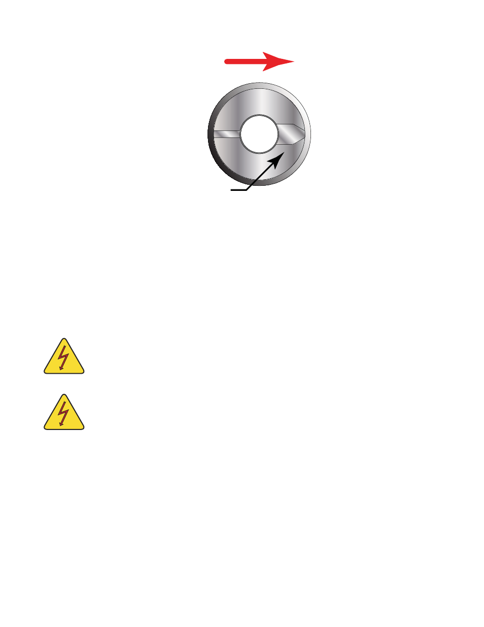
Flow Direction
Arrow
FIGURE 2.7 - FLOW DIRECTION ARROW
PROBE CABLES
Before inserting the probe into the pipe, the sensor cables should be routed to the transmitter location.
Verify that the supplied cable length is sufficient to meet the installation requirements. While transducer
cable extension is not generally recommended, if additional transducer cable length is required, utilize
cable and connectors of the correct type and impedance. In many cases, especially if a splice my be
exposed to water or other liquids, it may be more effective to replace the entire cable. Transducers use
RG59 ,75 ohm coaxial cable or Twinax (Belden #9463) or (Belden # 9463DB) 78 Ohm two conductor cable.
CAUTION: The probe cables are designed to carry low level signals that are developed by the
sensor. Care should be taken in routing the cables. Avoid running cables near sources of high
voltage or EMI/RFI. Also avoid routing the cables in cable tray configurations, unless the trays
are specifically used for other low voltage, low level signal cables.
CAUTION: The internal DP7 probe wiring is epoxy encapsulated to seal it from moisture. The
DP7 probe is provided with two coaxial cables to shield the low level signals and must be
continuous to the DP7 probe transmitter. Excess wire may be cutoff or simply coiled near the
DFX instrument.
PROBE RETRACTION PROCEDURE
1) Retract the probe by loosening the upper jam nuts counterclockwise as viewed from the top of
the probe using the proper size wrench. If the pipe is under pressure, the nuts must be turned
alternately about two turns at a time to prevent binding as a result of non-equal seal loading. In
many cases, the line pressure will cause the probe to retract. Should the probe bind, use the re-
traction nuts on the lower side of the probe flange to assist in the probe retraction. Continue this
procedure until the probe is fully retracted into the isolation valve.