Procedures are as follows – Dynasonics DDFXD Doppler Ultrasonic Flow Meter User Manual
Page 18
18
06-DPP-UM-00147 02/12
If the Bronze Hot Tap Kit (p.n. D030-1006-001) or Stainless Steel
Hot Tap Kit (p.n. D030-1006-002) accessory kits were ordered
with the DP7 probe, a hot tapped installation can be complet-
ed. The kits include an isolation valve assembly and are de-
signed for installation
in pipes under pres-
sure, up to 700 psi (48
Bar) at 70 °F (21 °C).
All items required for
installation are provid-
ed with the kit, except
for the 1½” NPT weld
coupling or service
saddle and the drilling
and welding equip-
ment. These instruc-
tions call for the use
of a drilling machine
designed for opera-
tions under pressure
(for example, Mueller
Co., Water Products Division).
PROCEDURES ARE AS FOLLOWS:
1) Verify that the pipe’s line pressure is within the rated limits of
the pressure drilling machine to be used.
2) Grind off paint or other coatings from the pipe in the area
where the DP7 Probe Assembly is to be installed.
3) Tack weld a 1½” NPT weld coupling to the pipe or install a ser-
vice saddle according to the supplier’s instructions. The coupling
or saddle must be aligned perpendicular to the pipe axis and square to its plane.
4) Complete welding. A water tight, 0.25” minimum weld bead is recommended.
5) Install the close nipple (supplied with assembly) into the weld coupling. Use appropriate pipe
sealants.
6) Install the isolating ball valve on the close nipple. Verify that the valve is in fully open position.
7) Install drill bit and adapter into the pressure drilling machine. Then attach the machine to the
isolation valve.
8) Drill through the pipe wall in accordance with the instructions supplied with the drilling machine.
9) Withdraw the drill bit through the isolating valve. Close the valve and remove the drilling ma-
chine. Check for leakage at valve and connections.
10) Place pipe sealant on the 1½” NPT threads of the insertion fitting assembly. Screw the assembly
into the isolation valve and tighten with a 2½” pump wrench.
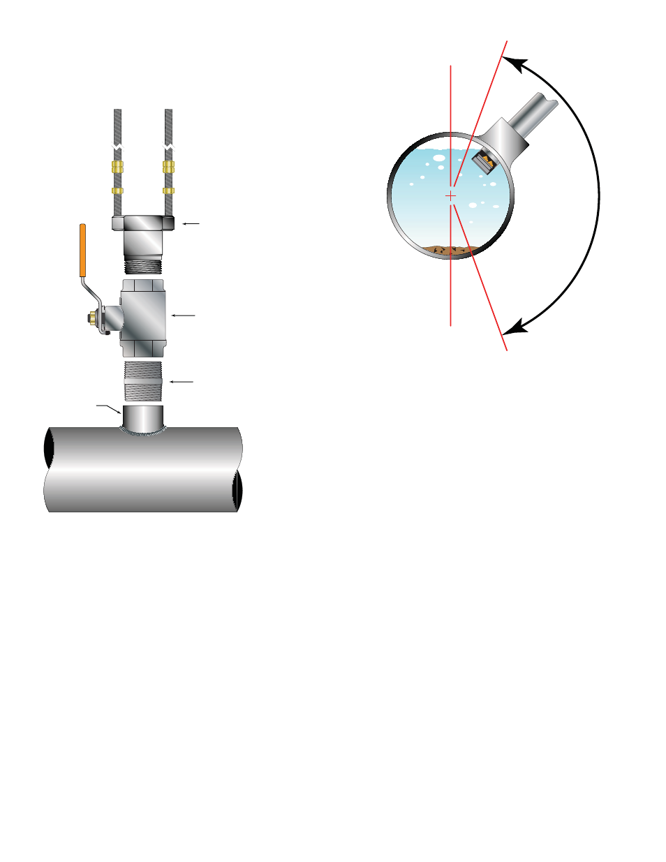
20°
20°
FIGURE 2.4 - INSTALLATION LOCATIONS
Full Port
Ball Valve
Close
Nipple
Weld
Coupling
Seal
Fitting
FIGURE 2.5 - HOT TAP INSTALLATION