BEI Sensors Anti-Dither Module User Manual
Page 2
7230 Hollister Ave, Goleta
Tel: (805) 968-0782 or (800) 350-2727
California, 93117 – 2891 USA Specification No. 02125-003 Rev0611 Fax: (805) 968-3154 or (800) 960-2726
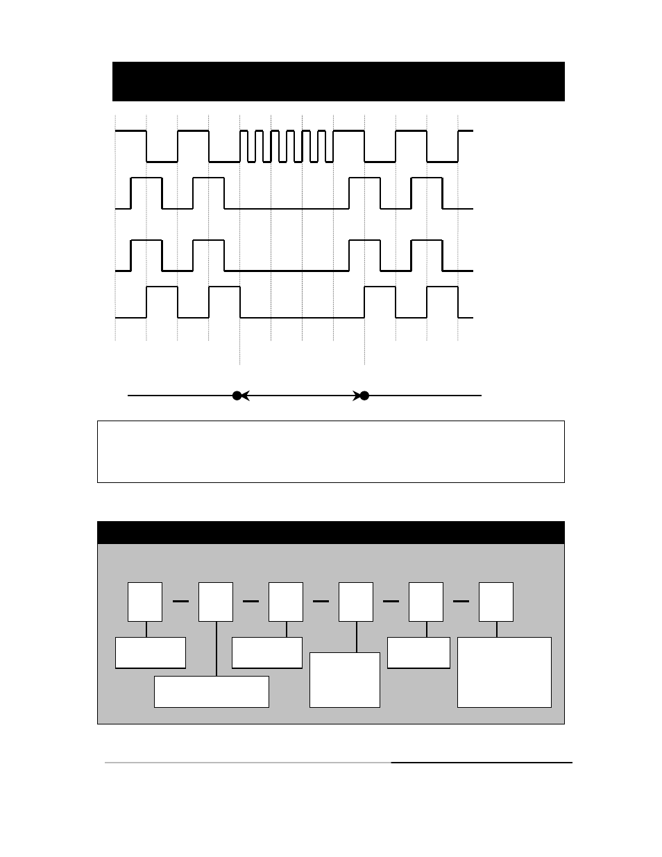
ENCODER
OUTPUTS
A CHANNEL
B CHANNEL
OUTPUT FROM ANTI-
DITHER MODULE
A’ CHANNEL
B’ CHANNEL
Mechanical system stop
-- Or -- vibration imposed
Dither or vibration – could
produce error in controller
Mechanical system restart
-- Or-- vibration removed
WAVEFORM DIAGRAM
ILLUSTRATING OPERATION OF THE ANTI-DITHER FUNCTION
Note: For simplicity of illustration, the inverted channels, A/ and B/ have not been shown.
The index, or Z, channel is also not shown in the above diagram but is passed through directly
as an optically isolated signal and maintains its original relationship to the encoder output
channel. Reference http://www.beisensors.com/pdfs/oim.pdf for connection diagrams.
Anti-Dither Module Order Options For assistance, call 800-350-2727
Use this diagram, working from left to right to construct your model number:
Example: EM-DR1-AD-24-TB-2
8
V/V
EM
AD
DR1
24
TB
2
8
V/V
EM = Electronic
Module
DR1 = 114.5mm X 99mm X
22.5mm DIN Rail Package
AD = Anti-Dither
Function
Output from
Encoder
5 = 5VDC
15 = 12-15 VDC
24 = 24VDC
TB = Terminal
Block
Supply Voltage/Output
from AD Module
28V/V: V
out
= V
in
28V/5: V
out
= 5 VDC
28V/OC: V
ou
t = Open
Collector
Note: Refer to BEI Opto Isolator Module Applications guide
for mechanical specifications and connection instructions.