BEI Sensors Serial to Parallel Converter Module User Manual
Electronic modules, Bei sensors, Divide-by module
Electronic Modules
Divide-By Module
BEI Sensors
7230 Hollister Avenue
Goleta, CA 93117
www.beisensors.com
Tel: 800-350-2727
Fax: 805-968-3154
Specification No.:02086-001
Rev 10-13
Electronic Modules
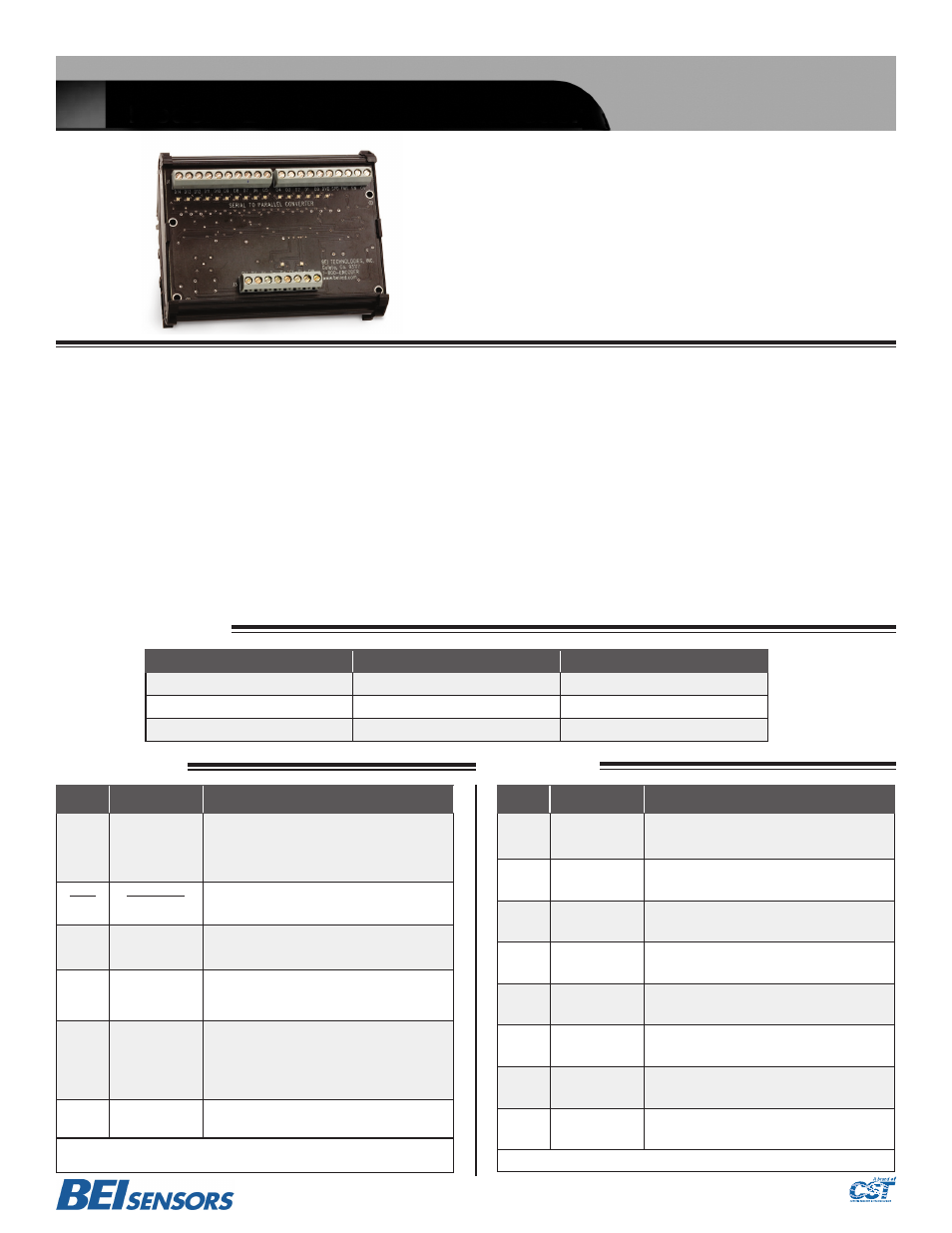
Serial to Parallel Converter for Absolute Encoders
BEI Sensors
BEI’
s serial-to-parallel converter module takes serial data from any
BEI
Serial Synchronous Interface (
S3
) or
RS
-
422
Interface (
S1
) encoders and converts
it to a parallel output. This eliminates the high cost and noise susceptibility of long, parallel cable runs, enabling the simplicity of a serial output encoder
and a low cost twisted pair cable to interface with a standard
PLC
or controller. The bright
LED
indicators give visual status for deserialization, testing and
troubleshooting.
Serial input, either
SSI
or
RS-422
is easily selectable by a Format Select terminal directly on the board. In
SSI
mode, the on-board clock generates pulses
to signal the encoder to provide data. Data is received serially and converted to a parallel format. Clock frequency is selectable by a Speed Select terminal,
again directly on the board. For
100
feet or less, the
1.25 MH
z mode can be used and for longer distances, up to
500
feet, a
200
k
H
z rate is available.
In
RS-422
mode, data is received asynchronously from the encoder and converted to a parallel format. Speed Select input is used to set the baud rate:
19.2
k
B
aud for most applications, up to
500
feet;
115.2
k
B
aud for shorter runs below
100
feet.
See the
BEI
specifications for Serial Synchronous Interface (
S3
) and
RS-422
for additional specifications, data format information and timing diagrams.
The module accepts inputs from
5
to
28 VDC
and provides three output options:
V
out =
V
in;
V
out =
5 V
; and
V
out =
O
pen
C
ollector. The compact
DIN
rail
package is
105
mm wide,
78
mm high and only
45
mm high and mounts to standard
DIN
Rail,
EN 50 022, 35
mm X
7.5
mm, included with the module.
Features:
•
SSI OR RS422 SELECTABLE ON BOARD
•
TWO TRANSMISSION RATES TO ACCOMMODATE LONG
CABLE RUNS
•
HIGH NOISE IMMUNITY
•
CAN BE USED FOR SYSTEM TROUBLESHOOTING
•
SAVES INSTALLATION COSTS
•
COMPACT PACKAGE
Output
BEI Model Number
BEI Part Number
5 - 28 Volts
EM-DR3-SP-5-TB-28V/V
60007-001
5 Volts
EM-DR3-SP-5-TB-28V/5
60007-002
Open Collector
EM-DR3-SP-5-TB-28V/OC
60007-003
Ordering Information:
Controller Side:
Encoder Side:
Pin
Description Notes
D14
thru
D0
Parallel Data
Outputs
For the SSI selection under pin FMT, data
is MSB justified.
For the RS422 selection under pin FMT,
data is LSB justified.
DVD
Data Valid
Logic LO = Data Valid
Logic HI = Data not valid (transitioning)
FMT
Format Select
Logic HI (N/C) = SSI
Logic LO (0V) = RS422 (Asynchronous)
EN
Output Enable
Logic HI (N/C) = Output active
Logic LO (0V) = Inactive (High Impedance)
SPD
Speed Select
SSI: Logic HI (N/C) = 1.25 MHz
Logic LO (0V) = 200kHz
RS422: Logic HI (N/C) = 19.2 kBaud
Logic LO (0V) = 115.2 kBaud
0V
Supply
Common
Logic LO available for format and speed
selections
NOTE: On Format, Enable and Speed selects, internal 10KΩ pull-ups to Vs provide default
Logic HI
Pin
Description Notes
0V
Supply
Common
Connect either 0V pin to power supply
common. This should be the same supply
common as used on the encoder.
0V
Supply
Common
Connected internally – see note above
Vs
Supply Voltage Provide 5 to 28 volts supply.
D -
Data minus
Connect to Data – line from encoder
D +
Data plus
Connect to Data + line from encoder
CL -
Clock minus
Connect to Clock - line from encoder (SSI
only). If using RS422, then N/C
CL +
Clock plus
Connect to Clock + line from encoder (SSI
only). If using RS422, then N/C
DIR
N/C
Leave this disconnected
NOTE: LED indicators on key data and control lines (Logic HI = Red, Logic Lo = Green)