Dimensions, Hmt25 absolute multi-turn encoder, 24 bit, ssi compatible output timing – BEI Sensors HMT25 Absolute Multi-Turn Encoder User Manual
Page 2
HMT25 Absolute Multi-Turn Encoder
PIN FUNCTION
(2)
T
F7
U
F6
V
F5
W
F4
X
F3
Y
F2
Z
F1
a
F0 (lSB)
Tables and Figures
Notes
Tel: 805-968-0782 /800-350-2727 | Fax: 805-968-3154 / 800-960-2726
7230 Hollister Ave., Goleta, CA 93117-2807 |
www.beisensors.com
1. Mounting is usually done either using the
D-style square flange mount, E- or G-style servo
mounts, or one of the standard face mounts, F1
for example. Consult factory for additional face
mount options.
2.The shaft seal is recommended in virtually all
installations. The most common exceptions are
applications requiring a very low starting torque
or those requiring operation at both high tem-
perature and high speed.
3. Output IC’s: Output IC’s are available as
either Line Driver (LD) or NPN Open Collector
(OC) types. Open Collectors require pull-up resis-
tors, resulting in higher output source imped-
ance (sink impedance is similar to that of line
drivers). In general, use of a Line Driver style
output is recommended. Line Drivers source or
sink current and their lower impedance mean
better noise immunity and faster switching
times.
Warning: Do not connect any line driver
outputs directly to circuit common/OV, which
may damage the driver. Unused outputs should
be isolated and left floating. Our applications
specialists would be pleased to discuss your
system requirements and the compatibility of
your receiving electronics with Line Driver
type outputs.
28V/V: Multi-voltage Line Driver (7272*): 100
mA source/sink. Input voltage 5 to 28 VDC +/-
5% standard (Note: Vout = Vin). This driver is
TTL compatible when used with 5 volt supply.
Supply lines are protected against overvoltage to
60 volts and reverse voltage. Outputs are short
circuit protected for one minute. Supply current
is 120 mA typical (plus load current). This is
the recommended replacement for 3904R and
7406R open collector outputs with internal pullup
resistors. It is also a direct replacement for any
4469, 88C30, 8830 or 26LS31 line driver.
28V/5: Multi-voltage Line Driver (7272*): 100
mA source/sink. Input voltage 5 to 28 VDC +/-
5% standard, internally regulated with 5V (TTL
compatible) logic out. Supply lines are protected
against overvoltage to 60 volts and reverse volt-
age. Outputs are short circuit protected for one
minute. Supply current is 90 mA typical (plus
load current).
Note: Limit encoder load to 2.5W
max at ambient. Example at 12 VDC: 2.5W/
(+12VDC minus +5VDC) = 357 mA total allowed
current. Consult factory for your specific require-
ments.
28V/OC: NPN Open Collector (3904*, 7273*).
Current sink of 80 mA max. Current sourced
by external pull- up resistor. Output can be
pulled up to voltage other than supply voltage
(30 V max). Input voltage 5 to 28 VDC
+
/- 5%
standard. Supply current is 120 mA typical. This
replaces prior IC’s with designations of 3904,
7406, 3302, 681 and 689.
4. Special –S at the end of the model number is
used to define a variety of non-standard features
such as special shaft lengths, voltage options,
or special testing. Please consult the factory to
discuss your special requirements.
* Products manufactured prior to April 2007 used the line driver IC number instead
of voltage output in model number.
Special note on vibration testing:
Test profile is 0.3 g’s ramp to 20 g’s from 5 to 40 Hz and 20 g’s from 40 Hz to 2000 Hz.
HMT25 Output Terminations for Parallel Output
1
PIN FUNCTION
(2)
A
T11 (MSB)
B
T10
C
T9
D
T8
e
T7
F
T6
G
T5
H
T4
PIN FUNCTION
(2)
J T3
K
T2
l
T1
M
T0 (lSB)
N F11 (MSB)
P
F10
R
F9
S
F8
PIN FUNCTION
(2)
b N/C
c
lATCH
d
DiR CoNTRol
e
eNABle (option)
f
N/C
g
0 V
h
+V
j
CASe GND
Direction of Count: The HMT25 comes standard with a Direction of Count bit. Normal operation is CW
increasing count when viewed from the shaft end. This pin is normally pulled HI internally. To reverse the count
direction, this pin must be pulled LO (Circuit Common). Optionally this can be designated as CCW increasing
count when HI, in which case LO will be CW increasing count.
Latch: Outputs are active and provide continuous information when this pin is HI. When this pin is pulled LO (Circuit
Common) the outputs are latched at the logic state that is present when the latch is applied and will stay latched until
this pin is no longer LO. This pin is pulled HI internally.
Enable (optional): This option allows the operator to momentarily deactivate the outputs from the encoder. This
may be useful in instances where the outputs from several different encoders must be sampled independently.
Output is active when this pin is HI. When pulled LO (Circuit Common) all outputs go to high impedance state (Tri-
state) and are inactive until the LO state is removed. This pin is pulled HI internally. To order this option on the HMT25
make sure the model number has –S on the end, followed by the description, –S = output enable.
RESET (Optional): The Reset pin (Pin J) is normally HI and is pulled up internally to the positive supply volt-
age.To activate the Reset function, Pin J must be pulled LO by connecting it to signal common for 1 second or
greater. This causes the present encoder position to be stored into non-volatile memory as an offset value and
the output of the encoder is then set to the value of “0”. The encoder will retain this offset even if the power
is turned off and on again. A new “0” position can be set by rotating the encoder shaft to a new position and
then activating the Reset pin again. To order this option for the HMT25, make sure the model number has –S
on the end followed by the description, –S = Reset.
(1) Parallel output uses a MS3112E18-32P, 32 Pin connector on the encoder body (2) TXX = Turns
counts, FXX = Fine resolution counts
TERM BOARD
FUNCTION
CABlE
CONNECTOR* (H38 & H40 ONlY)
H38
H40
DATA+
YEL
A
4 1
DATA-
WHT/YEL
H
7
7
CLOCK+
BLU
B
5
2
CLOCK-
WHT/BLU
I
8
8
DIrECTIOn Of COUnT Orn
C
6
3
EnABLE (Optional)
VIOLET
E
9
—
rESET (Optional)
WHT/Orn
J
10
9
+V (SUPPLY VOLTAGE) rED
D
3
4
0 V (CIrCUIT COMMOn) BLK
f
2
5
CASE GrOUnD
Grn
G
1 6
HMT25 Output Terminations for Optional 24 Bit SSI Ouput
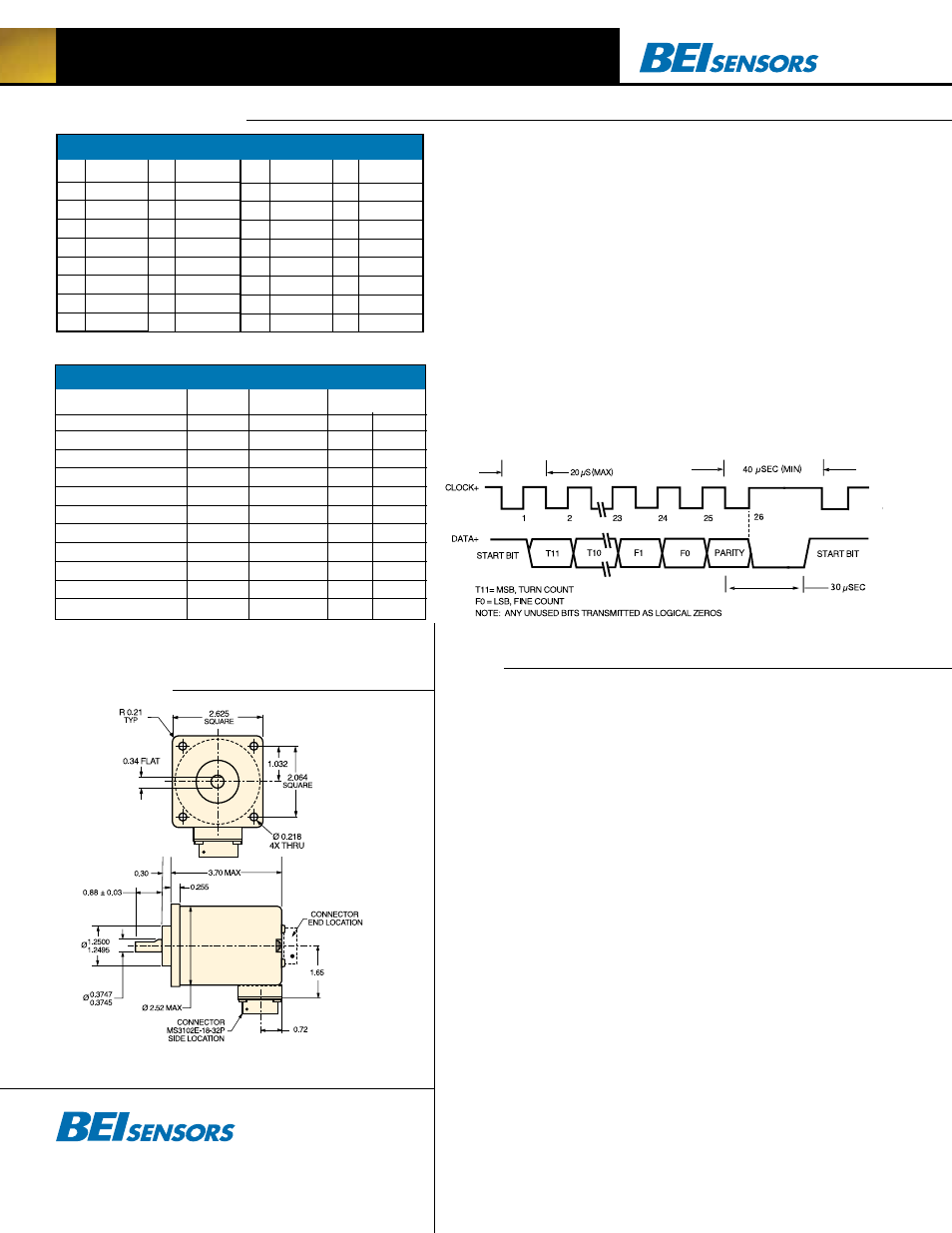
24 Bit, SSI Compatible Output Timing
*Connector is an MS3102E18-1P, 10-pin connector on the encoder body and mates to an MS3106F18-
1S connector or can be used with a standard cable/ connector assembly, BEI part 924-31186-18XX.
(Where XX = 10, 20, or 30 for a 10, 20 or 30 foot cable length.)
Dimensions