Figure 1 tables – BEI Sensors HS52 Incremental Explosion Proof Encoder User Manual
Page 2
Tel: 805-968-0782 /800-350-2727 | Fax: 805-968-3154 /800-960-2726 | 7230 Hollister Ave., Goleta, CA 93117-2807 |
www.beisensors.com
These commodities, technology or software if exported from the United States must be in accordance with the Bureau of Industry, and Security, Export Administration regulations. Diversion contrary to U.S. law is prohibited.
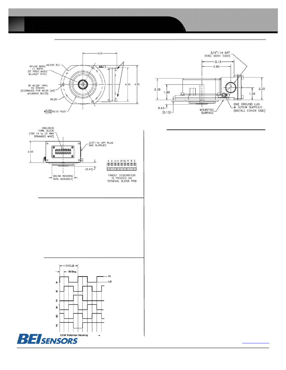
Dimensions
Notes
1. Non-standard index widths and multiple indices are available by special order. Consult
factory.
2. Complementary outputs are recommended for use with line driver type (source/sink)
outputs. When used with differential receivers, this combination provides a high degree of
noise immunity.
3. Output IC’s: Output IC's are available as either Line Driver (LD) or NPN Open Collector
(OC) types. Open Collectors require pull-up resistors, resulting in higher output source
impedance (sink impedance is similar to that of line drivers). In general, use of a Line Driver
style output is recommended. Line Drivers source or sink current and their lower impedance
mean better noise immunity and faster switching times. Warning: Do not connect any line
driver outputs directly to circuit common/OV, which may damage the driver. Unused outputs
should be isolated and left floating. Our applications specialists would be pleased to discuss
your system requirements and the compatibility of your receiving electronics with Line
Driver type outputs.
28V/V: Multi-voltage Line Driver (7272*): 100 mA source/sink. Input voltage 5 to 28 VDC +/-
5% standard (Note: Vout = Vin). This driver is TTL compatible when used with 5 volt supply.
Supply lines are protected against overvoltage to 60 volts and reverse voltage. Outputs are
short circuit protected for one minute. Supply current is 120 mA typical (plus load current).
This is the recommended replacement for 3904R and 7406R open collector outputs with
internal pullup resistors. It is also a direct replacement for any 4469, 88C30, 8830 or
26LS31 line driver
28V/5: Multi-voltage Line Driver (7272*): 100 mA source/sink. Input voltage 5 to 28 VDC +/-
5% standard, internally regulated with 5V (TTL compatible) logic out. Supply lines are
protected against overvoltage to 60 volts and reverse voltage. Outputs are short circuit
protected for one minute. Supply current is 90 mA typical (plus load current).
15V/V: Multi-voltage Line Driver (4469*): 100 mA source/sink. Input voltage 5 to 15 VDC +/-
5% standard (Note: Vout = Vin). TTL compatible when used with 5 volt supply. Supply lines
are protected against overvoltage to 60 volts and reverse voltage. Outputs are short circuit
protected for one minute. Supply current is 90 mA typical (plus load current). This is a direct
replacement for the 4469 Line Driver.
28V/OC: NPN Open Collector (3904*, 7273*). Current sink of 80 mA max. Current sourced
by external pull- up resistor. Output can be pulled up to voltage other than supply voltage
(30 V max). Input voltage 5 to 28 VDC +/- 5% standard. Supply current is 120 mA typical.
This replaces prior IC's with designations of 3904, 7406, 3302, 681 and 689.
5V/OCR, 15V/OCR, 24V/OCR: Open Collector (3904R*, 7406R*, 7273R*): Current sink of
70 mA max. Includes internal pull-ups sized at approximately 100 ohms/volt. Max current
source is 10 mA. Supply current is 100 mA typical, 120 mA with internal pull-ups. The
5V/OCR, 15V/OCR and 24V/OCR are often replaced by the 28V/V in system upgrades.
4. Special –S at the end of the model number is used to define a variety of non-standard
features such as special shaft lengths, voltage options, or special testing. Please consult
the factory to discuss your special requirements.
5. Higher frequency response may be available. Please consult with the factory.
6. Extended temperature ratings are available in the following ranges: -40 to 70ºC or -40 to
80ºC. Max temp extremes above 80°C to +105°C are available but will not be UL or
Cenelec certified. Extended temperature ranges can affect other performance factors.
Consult with factory for more specific information.
Encoder Installation
See specification no. 02131-002
Maintenance and Service
There are no user serviceable parts inside. Encoder must be returned to factory for service.
Model HS52 Explosion Proof
Hollow Shaft Incremental Encoder
BEI Sensors
Figure 1
Tables
Output Waveform
TABLE 1: Disc Resolutions
32 100 250 360 420
500
512 600 720 1000
1024
1200 1500 1650 1800
2000
2100 2048 2500 2881
3600
3600 3710 4096 5000
For interpolation please specify the multiplied output (up to 80,000) in the
model number, i.e. 80,000-T16.
Flange
Specification No. 02131-001 Rev 09-11
All measurements in inches
(M5x18 screws)