Figure 1, Hs20 incremental optical encoder, Output waveform – BEI Sensors HS20 Incremental Hollow Shaft Encoder User Manual
Page 2: Table 1-output termination pinouts, Table 2–hs20 disc resolutions, R2 tether arm hs20 diagram
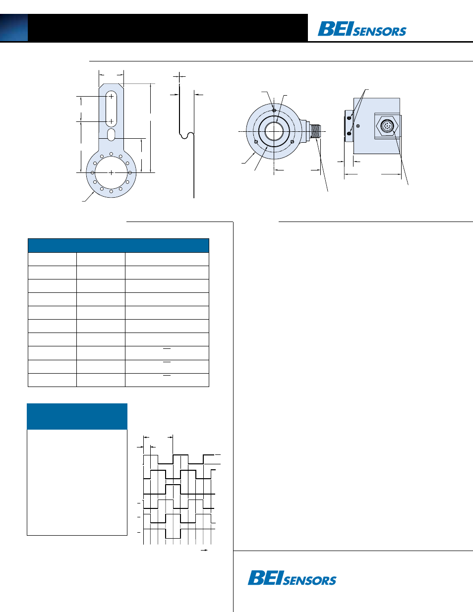
HS20 Incremental Optical Encoder
2.05±0.03
0.33
Ø 2.00
1.67 MAX
M12X1 CONN.
(2) #6 SET SCREW
NOTE: CONN. KEY
POSITION VARIES
HS20 Outline
2.05±0.03
1.00
Ш 2.00
3.56±0.03
1.37
Ш(BORE +0.0005)
+0.001/-0.000 THRU
0.60
0.02
1.00
R2 Tether Arm
3X #4-40 UNC-2B
X .25 DP. MIN
EQL SP ON
A Ø1.50 BC
2.05±0.03
0.33
Ø 2.00
1.67 MAX
M12X1 CONN.
(2) #6 SET SCREW
NOTE: CONN. KEY
POSITION VARIES
HS20 Outline
2.05±0.03
1.00
Ш 2.00
3.56±0.03
1.37
Ш(BORE +0.0005)
+0.001/-0.000 THRU
0.60
0.02
1.00
R2 Tether Arm
3X #4-40 UNC-2B
X .25 DP. MIN
EQL SP ON
A Ø1.50 BC
2.05±0.03
0.33
Ø 2.00
1.67 MAX
M12X1 CONN.
(2) #6 SET SCREW
NOTE: CONN. KEY
POSITION VARIES
HS20 Outline
2.05±0.03
1.00
Ш 2.00
3.56±0.03
1.37
Ш(BORE +0.0005)
+0.001/-0.000 THRU
0.60
0.02
1.00
R2 Tether Arm
3X #4-40 UNC-2B
X .25 DP. MIN
EQL SP ON
A Ø1.50 BC
2.05±0.03
0.33
Ø 2.00
1.67 MAX
M12X1 CONN.
(2) #6 SET SCREW
NOTE: CONN. KEY
POSITION VARIES
HS20 Outline
2.05±0.03
1.00
Ш 2.00
3.56±0.03
1.37
Ш(BORE +0.0005)
+0.001/-0.000 THRU
0.60
0.02
1.00
R2 Tether Arm
3X #4-40 UNC-2B
X .25 DP. MIN
EQL SP ON
A Ø1.50 BC
R2 Tether Arm
HS20 Diagram
Dimensions
Tables and figures
notes
Table 1-Output Termination Pinouts
Pin (K8)
Wire
function
1
YEL
A
4
BLU
B
6
ORN
Z
2
RED
+V (SUPPLY)
7
BLK
OV (CIRCUIT COMMON)
N/C
GRN
CASE GROUND
3
W/YEL
A
5
W/BLU
B
8
W/ORN
Z
1. The typical hollow shaft product is supported by, and clamped to, the driving shaft. A flexible tether is used to
keep the housing from rotating.
2. The rubber shaft seal is recommended in virtually all installations. The most common exceptions are
applications requiring a very low starting torque or those requiring operation at both high temperature and
high speed. For these exceptions, a felt shaft seal is recommended. Felt seals require very low start-
ing torque and can virtually eliminate frictional heat. Encoders ordered with felt shaft seals will have an
enclosure rating of IP50 and will have less than 1/10th the Starting Torque specified under Mechanical
Configurations.
3. Non-standard index widths and multiple indices are available by special order. Consult factory.
4. Complementary outputs are recommended for use with line driver type (source/sink) outputs. When used
with differential receivers, this combination provides a high degree of noise immunity.
5. output iC’s: Output IC’s are available as either Line Driver (LD) or NPN Open Collector (OC) types.
Open Collectors require pull-up resistors, resulting in higher output source impedance (sink impedance is
similar to that of line drivers). In general, use of a Line Driver style output is recommended. Line Drivers
source or sink current and their lower impedance mean better noise immunity and faster switching times.
Warning: Do not connect any line driver outputs directly to circuit common/OV, which may damage the
driver. Unused outputs should be isolated and left floating. Our applications specialists would be pleased
to discuss your system requirements and the compatibility of your receiving electronics with Line Driver
type outputs.
28V/V: Multi-voltage Line Driver (7272*): 100 mA source/sink. Input voltage 5 to 28 VDC +/- 5% standard
(Note: V
out
= V
in
). This driver is TTL compatible when used with 5 volt supply. Supply lines are protected
against overvoltage to 60 volts and reverse voltage. Outputs are short circuit protected for one minute.
Supply current is 120 mA typical (plus load current). This is the recommended replacement for 3904R and
7406R open collector outputs with internal pullup resistors. It is also a direct replacement for any 4469,
88C30, 8830 or 26LS31 line driver
28V/5: Multi-voltage Line Driver (7272*): 100 mA source/sink. Input voltage 5 to 28 VDC +/- 5% stan-
dard, internally regulated with 5V (TTL compatible) logic out. Supply lines are protected against overvoltage
to 60 volts and reverse voltage. Outputs are short circuit protected for one minute. Supply current is 90
mA typical (plus load current).
28V/oC: NPN Open Collector (3904*, 7273*). Current sink of 80 mA max. Current sourced by external
pull- up resistor. Output can be pulled up to voltage other than supply voltage (30 V max). Input voltage 5
to 28 VDC
+
/- 5% standard. Supply current is 120 mA typical. This replaces prior IC’s with designations of
3904, 7406, 3302, 681 and 689.
5V/oCr, 15V/oCr, 24V/oCr: Open Collector (3904R*, 7406R*, 7273R*): Current sink of 70 mA
max. Includes internal pull-ups sized at approximately 100 ohms/volt. Max current source is 10 mA.
Supply current is 100 mA typical, 120 mA with internal pull-ups. The 5V/OCR, 15V/OCR and 24V/OCR
are often replaced by the 28V/V in system upgrades.
5V/V. 5V/oC, 5V/oCr and 9V/oC can be intrinsically safe line driver and open collector outputs avail-
able on certain model variations. They are intrinsically safe only when installed per the controldrawing
noted on the certification label affixed to the encoder body.
6. Special –S at the end of the model number is used to define a variety of non-standard features such as
special shaft lengths, voltage options, or special testing. Please consult the factory to discuss your special
requirements.
7. Higher frequency response may be available. Please consult with the factory.
8. Extended temperature ratings are available in the following ranges:
-40 to 70°C, -40 to 85°C, –20 to 105°C and –40 to 105°C depending on the particular model. Some
models can operate down to
-55°C. Extended temperature ranges can affect other performance factors. Consult with factory for more
specific information.
9. Mating plug receptacles and mating cable assemblies may be ordered from the factory.
Tel: 805-968-0782 /800-350-2727
Fax: 805-968-3154 / 800-960-2726
7230 Hollister Ave., Goleta, CA 93117-2807
www.beisensors.com
Ø 1.13
1 CYCLE
90 Deg.
HI
A
B
Z
LO
CCW Rotation Viewing Face
A
B
Z
figure 1
Output Waveform
1* 2 3 5
6
8 10 11
12 24 25 30 32 40
50 60 64 75 80 95
100 105 115 120 125
150 192 200 240 250
256 300 336 360 400
500 510 512 600 625
635 720 785 1000 1024
1200**
Table 2–HS20
Disc Resolutions
resolutions shown in
rED
are not available as
express encoders
*No index. For interpolation please specify the
multiplied output (up to 4,096 for HS20) in the
model number, i.e. 4,096-T4.
**Consult factory for this resolution