H38 incremental optical encoder, Ul cen rear view, Table 1–output functions – BEI Sensors H38 Incremental Explosion-Proof Encoder User Manual
Page 2
H38 Incremental Optical Encoder
1. Non-standard index widths and multiple indices are available by
special order. Consult factory.
2. Complementary outputs are recommended for use with line driver
type (source/sink) outputs. When used with differential receivers, this
combination provides a high degree of noise immunity.
3. Output IC’s: Output IC’s are available as either Line Driver
(LD) or NPN Open Collector (OC) types. Open Collectors require
pull-up resistors, resulting in higher output source impedance
(sink impedance is similar to that of line drivers). In general, use
of a Line Driver style output is recommended. Line Drivers source
or sink current and their lower impedance mean better noise
immunity and faster switching times.
Warning: Do not connect
any line driver outputs directly to circuit common/OV. Those may
damage the driver. Unused outputs should be isolated and left
floating. Our applications specialists would be pleased to discuss
your system requirements and the compatibility of your receiving
electronics with Line Driver type outputs.
28V/V: Multi-voltage
Line Driver (7272*): 100 mA source/sink. Input voltage 5 to 28
VDC +/- 5% standard (Note: V
out
= V
in
). This driver is TTL com-
patible when used with 5 volt supply. Supply lines are protected
against overvoltage to 60 volts and reverse voltage. Outputs are
short circuit protected for one minute. Supply current is 120 mA
typical (plus load current). This is the recommended replacement
for 3904R and 7406R open collector outputs with internal pullup
resistors. It is also a direct replacement for any 4469, 88C30,
8830 or 26LS31 line driver
28V/5: Multi-voltage Line Driver
(7272*): 100 mA source/sink. Input voltage 5 to 28 VDC +/- 5%
standard, internally regulated with 5V (TTL compatible) logic out.
Supply lines are protected against overvoltage to 60 volts and
reverse voltage. Outputs are short circuit protected for one min-
ute. Supply current is 90 mA typical (plus load current).
15V/V:
Multi-voltage Line Driver (4469*): 100 mA source/sink. Input volt-
age 5 to 15 VDC +/- 5% standard (Note: V
out
= V
in
). TTL com-
patible when used with 5 volt. Supply lines are protected against
overvoltage to 60 volts and reverse voltage. Outputs are short
circuit protected for one minute. Supply current is 90 mA typical
(plus load current). This is a direct replacement for the 4469 Line
Driver.
28V/OC: NPN Open Collector (3904*, 7273*). Current
sink of 80 mA max. Current sourced by external pull- up resistor.
Output can be pulled up to voltage other than supply voltage (30 V
max). Input voltage 5 to 28 VDC
+
/- 5% standard. Supply current
is 120 mA typical. This replaces prior IC’s with designations of
3904, 7406, 3302, 681 and 689.
5V/OCR, 15V/OCR, 24V/OCR:
Open Collector (3904R*, 7406R*, 7273R*): Current sink of 70 mA
max. Includes internal pull-ups sized at approximately 100 ohms/
volt. Max current source is 10 mA. Supply current is 100 mA
typical, 120 mA with internal pull-ups. The 5V/OCR, 15V/OCR and
24V/OCR are often replaced by the 28V/V in system upgrades.
4. Special –S at the end of the model number is used to define
a variety of non-standard features such as special shaft lengths,
voltage options, or special testing. Please consult the factory to
discuss your special requirements.
5. Higher frequency response may be available. Please consult
with the factory.
6. Extended temperature ratings are available in the following
ranges: -40 to 70°C, -40 to 85°C, –20 to 105°C and –40 to
105°C depending on the particular model. Extended temperature
ranges can affect other performance factors. Consult with factory
for more specific information.
Encoder Installation:
1. Environment: Hazardous Locations — UL Complies with UL and
cUL Class Groups D, Div.1;
CEN Complies with UL2 requirements
plus CENELAC/ATEX EEx d IIB T4.
2. WARNING: Open all circuits prior to connections of this product
to power and controller.
3. The installation must comply with NEC Class II circuits or with
the regulations of the country of use.
4. AWG 14 - 22 stranded wire stripped to .25” [6.3mm} is recommended.
5. Use 105° C minimum rated cable/conductors housed within an
approved rigid conduit.
6. Conduit runs must have a sealing fitting certified to EN5Q018 as
EEx d IIB immediately at the entrance to the device.
7. Tightly close terminal block access cover prior to applying power.
8. For maximum bearing life, a flexible coupling is recommended
between encoder shaft and driving shaft.
During Use:
1. Keep terminal block access tightly secured during use.
2. DO NOT loosen two 5/16” set screws at opposite face.
Maintenance and Service:
1. There are no user serviceable parts inside. Encoder must be
returned to factory for service.
2. WARNING: Open all circuits to this product prior to opening
access cover to disconnect wires.
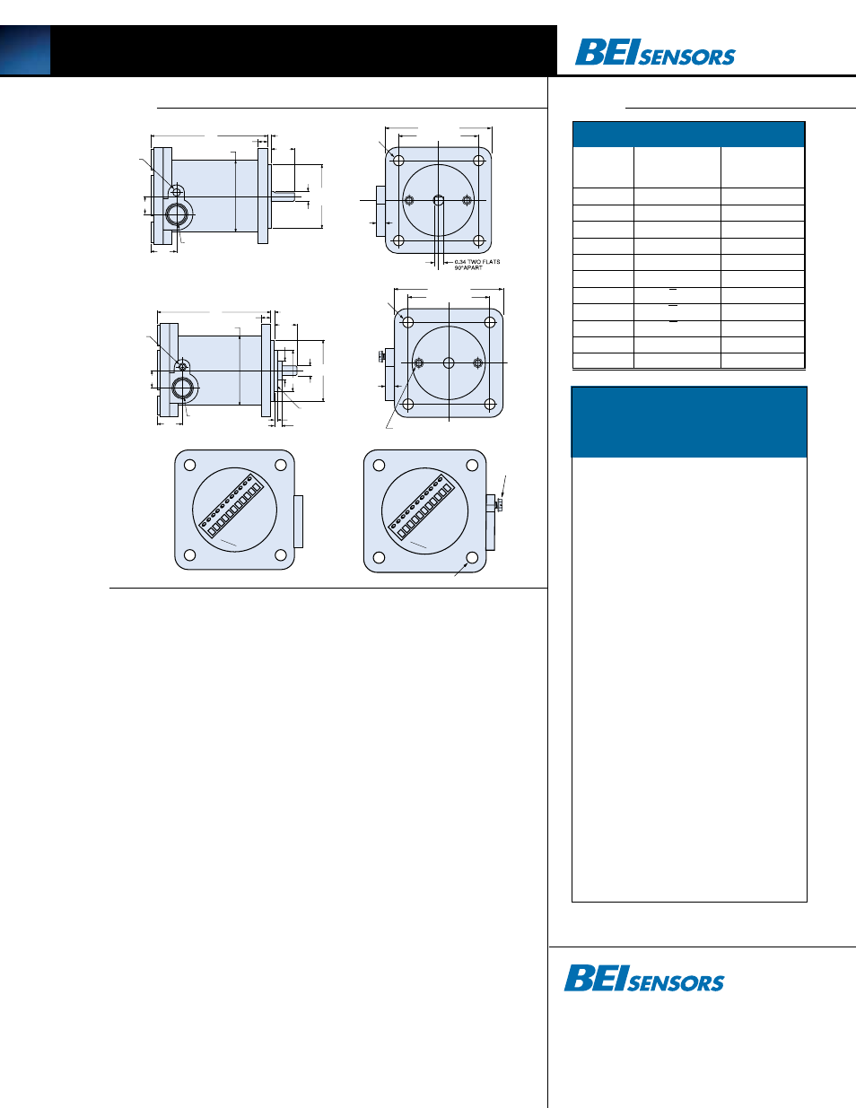
Dimensions
Notes
Tables
Tel: 805-968-0782 /800-350-2727
Fax: 805-968-3154 / 800-960-2726
7230 Hollister Ave., Goleta, CA 93117-2807
www.beisensors.com
1 2
3 4
5 6
7 8
9
0
1
1
1
V
G
D
N
G
E
S
A
C
4.5 7
LABYRINTH SEA L
ADDED FOR CLASS I I
2.8 4
0.374 7
0.374 5
0.3 8
Ø 0.62
1.5 0
0.12 5
0.31 2
. 125
0.88
0.98
0.66
± 0.06
O-RING SEAL
1/2-14NPSF (DRYSEAL)
STRAIGHT PIPE THREADS
2.49 9
2.49 6
0.32
Ø 0.390
(4)
3.75 SQUARE
2.828 SQUARE
Ш
Ш
Ш
1 2
3 4
5 6
7 8
9 1
011
G
V
CASE GND
4.57
LABYRINTH SEAL
Ш 2.84
0.3747
0.3745
0.38
Ш 0.62
1.50
0.14
0.312
.125
0.88
0.98
0.66
± 0.06
1/2-14NPSF (DRYSEAL)
STRAIGHT PIPE THREADS
(CEN) FRONT SCREWS ARE COVERED
2.499
2.496
0.32
Ø 0.390 (4X)
3.75 SQUARE
2.828 SQUARE
1 2
3 4
5 6
7 8
9 1
011
G
V
CASE GND
4.57
(CEN)
EARTHING
SCREW
1/4-20 SCREWS (UL, UL2)
M6x1 SCREWS (CEN)
0.26
2.84
0.3747
0.3745
0.38
.125
0.88
0.98
0.66
± 0.06
1/2-14NPSF (DRYSEAL)
STRAIGHT PIPE THREADS
2.499
2.496
0.32
Ø 0.390 (4X)
0.34 TWO FLATS
90°APART
3.75 SQUARE
2.828 SQUARE
Ш
Ш
Ш
Ш
Ш
Ш
UL
CEN
Rear View
1 2
3 4
5 6
7 8
9
0
1
1
1
V
G
D
N
G
E
S
A
C
4.5 7
LABYRINTH SEA L
ADDED FOR CLASS I I
2.8 4
0.374 7
0.374 5
0.3 8
Ø 0.62
1.5 0
0.12 5
0.31 2
. 125
0.88
0.98
0.66
± 0.06
O-RING SEAL
1/2-14NPSF (DRYSEAL)
STRAIGHT PIPE THREADS
2.49 9
2.49 6
0.32
Ø 0.390
(4)
3.75 SQUARE
2.828 SQUARE
Ш
Ш
Ш
1 2
3 4
5 6
7 8
9 1
0 11
G
V
CASE GND
4.57
LABYRINTH SEAL
Ш 2.84
0.3747
0.3745
0.38
Ш 0.62
1.50
0.14
0.312
.125
0.88
0.98
0.66
± 0.06
1/2-14NPSF (DRYSEAL)
STRAIGHT PIPE THREADS
(CEN) FRONT SCREWS ARE COVERED
2.499
2.496
0.32
Ø 0.390 (4X)
3.75 SQUARE
2.828 SQUARE
1 2
3 4
5 6
7 8
9 1
011
G
V
CASE GND
4.57
(CEN)
EARTHING
SCREW
1/4-20 SCREWS (UL, UL2)
M6x1 SCREWS (CEN)
0.26
2.84
0.3747
0.3745
0.38
.125
0.88
0.98
0.66
± 0.06
1/2-14NPSF (DRYSEAL)
STRAIGHT PIPE THREADS
2.499
2.496
0.32
Ø 0.390 (4X)
0.34 TWO FLATS
90°APART
3.75 SQUARE
2.828 SQUARE
Ш
Ш
Ш
Ш
Ш
Ш
1 2
3 4
5 6
7 8
9 1
011
G
V
CASE GND
4.57
LABYRINTH SEAL
Ш 2.84
0.3747
0.3745
0.38
Ш 0.62
1.50
0.14
0.312
.125
0.88
0.98
0.66
± 0.06
1/2-14NPSF (DRYSEAL)
STRAIGHT PIPE THREADS
(CEN) FRONT SCREWS ARE COVERED
2.499
2.496
0.32
Ø 0.390 (4X)
3.75 SQUARE
2.828 SQUARE
1 2
3 4
5 6
7 8
9 1
011
G
V
CASE GND
4.57
(CEN)
EARTHING
SCREW
1/4-20 SCREWS (UL, UL2)
M6x1 SCREWS (CEN)
0.26
2.84
0.3747
0.3745
0.38
.125
0.88
0.98
0.66
± 0.06
1/2-14NPSF (DRYSEAL)
STRAIGHT PIPE THREADS
2.499
2.496
0.32
Ø 0.390 (4X)
0.34 TWO FLATS
90°APART
3.75 SQUARE
2.828 SQUARE
Ш
Ш
Ш
Ш
Ш
Ш
Table 1–Output Functions
8 BIT
TERMINAL
INCREMENTAL
GRAY CODE
PIN NO.
OUTPUT
OUTPUT*
1
CASE GRND.
CASE GRND.
2
OV
OV
3
+V
+V
4
A
G0
5
B
G1
6
Z
G2
7
A
G3
8
B
G4
9
Z
G5
10
SPARE
G6
11
SPARE
G7
Table 2 –Disc Resolutions
for Incremental Encoder
Model H38
1, 2, 3, 5, 6, 7, 8, 10, 13, 16, 20, 24, 25, 26,
30, 32, 33, 34, 36, 37, 40, 45, 48, 50, 51, 56*,
60, 64, 66, 72, 75, 80, 86, 88, 90, 100, 102,
120, 122,125, 127, 128, 132, 144, 148, 150,
158, 160, 175, 176, 180, 187, 192, 200, 202,
204*, 217, 220, 240, 250, 254, 255, 256, 264*,
274, 280, 283, 288, 292, 300, 312, 320, 321,
325, 360, 366, 372, 375, 377, 380, 381, 384,
385, 393, 400, 430, 432, 450, 462, 480, 490,
500, 502, 508, 512, 522, 530, 550, 560*, 576,
598, 600, 604, 625, 628, 635, 638, 640, 660,
672, 676, 680, 687, 690, 700, 720, 725, 735,
740, 744, 748, 750, 762, 768, 780, 785, 800,
812, 825, 850, 864, 878, 888, 900, 912, 914,
938, 942, 955, 960, 1000, 1016, 1024, 1030,
1035, 1036, 1040, 1054, 1056, 1074, 1076,
1080,1088, 1100, 1101, 1125, 1136, 1200,
1237, 1250, 1257, 1270, 1280, 1300, 1314,
1332, 1333, 1390, 1400, 1414, 1427, 1440,
1484, 1500, 1562, 1570, 1596, 1600, 1650,
1666, 1718, 1745, 1774, 1800, 1840*, 1850,
1855, 1875, 1894, 1920, 1952, 1968, 1979,
1995, 2000, 2048, 2080, 2094, 2100, 2160,
2164, 2199, 2200, 2250, 2356, 2400, 2485,
2500, 2514, 2519, 2540, 3000, 3125, 3600,
4000, 4096, 5000
*AB or ABC output only.
NOTE: Resolutions up to 72,000 are available.