Omnicoder, Model h25, Table 1 – BEI Sensors H25 Shafted Incremental Encoder User Manual
Page 2: Output waveform, Incremental output terminations, Installing the driver and software, Programming the omnicoder, For reference: old color of drawings
Omnicoder
®
Model H25
®
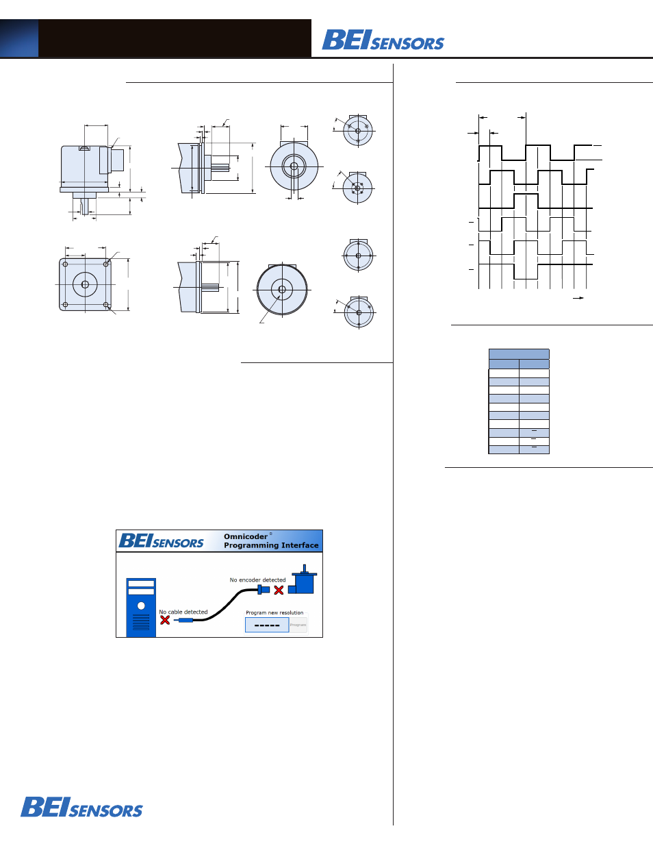
1 CYCLE
90 Deg.
HI
A
B
Z
LO
CCW Rotation Viewing Shaft
A
B
Z
Output Waveform
0.88 ± 0.03
1.38
Ø 2.500
0.100
.100 MIN
Ø 2.275
1.2500
1.2495
0.300
NOTE: SHAFT SEAL NOT
AVAILABLE ON H25G
0.34
2.500
2.498
Ø 2.625
0.125
0.125
0.88 ± 0.03
30°
10-32 UNF-2B
0.188 Min. Deep
3 places equally spaced
on a Ø 1.875 bolt circle.
4-40 UNC-2B
0.250 Min. Deep
4 places equally spaced
on a Ø 1.272 bolt circle.
(0.900 square, Ref.)
4-40 UNC-2B
0.250 Min. Deep
4 places equally spaced
on a Ø 2.00 bolt circle.
6-32 UNC-2B
0.250 Min. Deep
3 places equally spaced
on a Ø 2.00 bolt circle.
45°
30°
F1
F2 (H25G Only)
4-40 UNC-2B
0.250 Min. Deep
4 places equally spaced
on a Ø 1.272 bolt circle.
(0.900 square, Ref.)
45°
F2
F3
F4
MS STYLE
CONNECTOR
1.30 (SM16)
1.65 (SM 18)
EM CONNECTOR
POSITION
SM CONNECTOR
POSITION
2.50
0.255
0.30
Ø 2.52
MAX
1.2500
1.2495
2.064 TYP
2.625
SQUARE
Ø 0.218 4 HOLES
(Ø 2.919 B.C. REF)
1.032
0.21 R
0.3747
0.3745
0.88 ± 0.03
Ш
Ш
Ш
Ш
For Reference: Old Color of Drawings:
0.88 ± 0.03
1.38
Ø 2.500
0.100
.100 MIN
Ø 2.275
1.2500
1.2495
0.300
NOTE: SHAFT SEAL NOT
AVAILABLE ON H25 G
0.34
2.500
2.498
Ø 2.625
0.125
0.125
0.88 ± 0.03
30°
10-32 UNF-2B
0.188 Min. Deep
3 places equally spaced
on a Ø 1.875 bolt circle.
4-40 UNC-2B
0.250 Min. Deep
4 places equally spaced
on a Ø 1.272 bolt circle.
(0.900 square, Ref.)
4-40 UNC-2B
0.250 Min. Deep
4 places equally spaced
on a Ø 2.00 bolt circle.
6-32 UNC-2B
0.250 Min. Deep
3 places equally spaced
on a Ø 2.00 bolt circle.
45°
30°
F1
F2 (H25G Only)
4-40 UNC-2B
0.250 Min. Deep
4 places equally spaced
on a Ø 1.272 bolt circle.
(0.900 square, Ref.)
45°
F2
F3
F4
1.30 (SM16)
1.65 (SM 18)
SM CONNECTOR
POSITION
2.50
0.255
0.30
Ø 2.52
MAX
1.2500
1.2495
2.064 TYP
2.625
SQUARE
Ø 0.218 4 HOLES
(Ø 2.919 B.C. REF)
1.032
0.21 R
0.3747
0.3745
0.88 ± 0.03
Ш
Ш
Ш
Ш
For Reference: Old Color of Drawings:
Optional Face Mounts
H25D - Square Flange
H25E - 2.50 Servo Mount
H25G - 2.62 Dia Servo Mount
Incremental Output Terminations
TOLERANCES: .XX = ± 0.01, .XXX = ± 0.005
1. Mounting is usually done either using the D-style square flange mount,
E- or G-style servo mounts, or one of the standard face mounts, F1 for
example. Consult factory for additional face mount options.
2.The shaft seal is recommended in virtually all installations. The most
common exceptions are applications requiring a very low starting torque
or those requiring operation at both high temperature and high speed.
3. Output IC’s: Output IC’s are available as either Line Driver (LD) or
NPN Open Collector (OC) types. Open Collectors require pull-up resis-
tors, resulting in higher output source impedance (sink impedance
is similar to that of line drivers). In general, use of a Line Driver style
output is recommended. Line Drivers source or sink current and their
lower impedance mean better noise immunity and faster switching
times.
Warning: Do not connect any line driver outputs directly to
circuit common/OV, which may damage the driver. Unused outputs
should be isolated and left floating. Our applications specialists would
be pleased to discuss your system requirements and the compatibility
of your receiving electronics with Line Driver type outputs.
28V/V: Multi-voltage Line Driver (7272): 100 mA source/sink. Input
voltage 5 to 28 VDC +/- 5% standard (Note: Vout = Vin). This driver is
TTL compatible when used with 5 volt supply. Supply lines are protected
against overvoltage to 60 volts and reverse voltage. Outputs are short cir-
cuit protected for one minute. Supply current is 120 mA typical (plus load
current). This is the recommended replacement for 3904R and 7406R
open collector outputs with internal pullup resistors. It is also a direct
replacement for any 4469, 88C30, 8830 or 26LS31 line driver use
4. Special –S at the end of the model number is used to define a variety of
non-standard features such as special shaft lengths, voltage options, or spe-
cial testing. Please consult the factory to discuss your special requirements.
5. Higher frequency response may be available. Consult factory.
6. Mating straight plug receptacles may be ordered from the factory:
For M18 use MS3106F18-1S
Manufactured under U.S.patent numbers 7,349,821, 6,789,041
7,336,756
Model H25® and Omnicoder® are trademarks of BEI Sensors &
Systems Company.
Dimensions
Installation and Programming
Notes
Figure 1
0.88 ± 0.03
1.38
Ø 2.500
0.100
.100 MIN
Ø 2.275
1.2500
1.2495
0.300
NOTE: SHAFT SEAL NOT
AVAILABLE ON H25G
0.34
2.500
2.498
Ø 2.625
0.125
0.125
0.88 ± 0.03
30°
10-32 UNF-2B
0.188 Min. Deep
3 places equally spaced
on a Ø 1.875 bolt circle.
4-40 UNC-2B
0.250 Min. Deep
4 places equally spaced
on a Ø 1.272 bolt circle.
(0.900 square, Ref.)
4-40 UNC-2B
0.250 Min. Deep
4 places equally spaced
on a Ø 2.00 bolt circle.
6-32 UNC-2B
0.250 Min. Deep
3 places equally spaced
on a Ø 2.00 bolt circle.
45°
30°
F1
F2 (H25G Only)
4-40 UNC-2B
0.250 Min. Deep
4 places equally spaced
on a Ø 1.272 bolt circle.
(0.900 square, Ref.)
45°
F2
F3
F4
MS STYLE
CONNECTOR
1.30 (SM16)
1.65 (SM 18)
EM CONNECTOR
POSITION
SM CONNECTOR
POSITION
2.50
0.255
0.30
Ø 2.52
MAX
1.2500
1.2495
2.064 TYP
2.625
SQUARE
Ø 0.218 4 HOLES
(Ø 2.919 B.C. REF)
1.032
0.21 R
0.3747
0.3745
0.88 ± 0.03
Ш
Ш
Ш
Ш
For Reference: Old Color of Drawings:
Table 1
Tel: 805-968-0782 /800-350-2727 | Fax: 805-968-3154 / 800-960-2726
7230 Hollister Ave., Goleta, CA 93117-2807 |
www.beisensors.com
INSTALLING THE DRIVER AND SOFTWARE
Step 1
Go to
www.beisensors.com/downloads to view the download page
Step 2
Click on the “Windows: USB Virtual COM Port Driver” and save the file to your hard drive.
(Omnicoder Programming is currently supported on WIndows only).
Step 3
Unzip the USB driver to a directory on your hard drive
Step 4
Run “setup” to install drivers
Step 5
From the BEI download web page, click on the “Windows: Omnicoder Program” and save the file
to your hard drive
Step 6
Unzip the program to a directory on the hard drive.
Step 7
Run “setup” to install the Omnicoder Programming software.
Step 8
The program should start automatically. You have finished installing the software and are
now ready to program your Omnicoder. (All Omnicoders are shipped pre-programmed for 1024 CPT).
Below is a screen shot of the program interface.
PROGRAMMING THE OMNICODER
Step 9
Using the Omnicoder programming cable, plug the USB connector end into your PC.
The red X (No cable detected) should change to a green check mark, indicating that the
USB Programming Module was detected. (This may take up to 15 seconds)
Step 10 Plug the M18 connector end into the Omnicoder unit. The red X (No encoder detected)
should change to a green check mark, and the current Omnicoder resolution will be
displayed on your computer screen.
Step 11 To change the Omnicoder resolution, enter a new resolution as an integer between 1 and 10000 in the
box labeled “Program New Resolution.” Then click the “Program” button. In a few seconds, the
new resolution will be uploaded to the Omnicoder. The Omnicoder is now programmed and can be
disconnected. To program a new resolution, repeat Steps 9-11.
M18 CONNECTOR
PIN
CHANNEL
A
A
B
B
C
Z
D
+V
E
—
F
0V
G
CG
H
A
I
B
J
Z