Smart edge fx - ref. ste200 rear panel description – Analog Way Smart Edge FX User Manual
Page 3
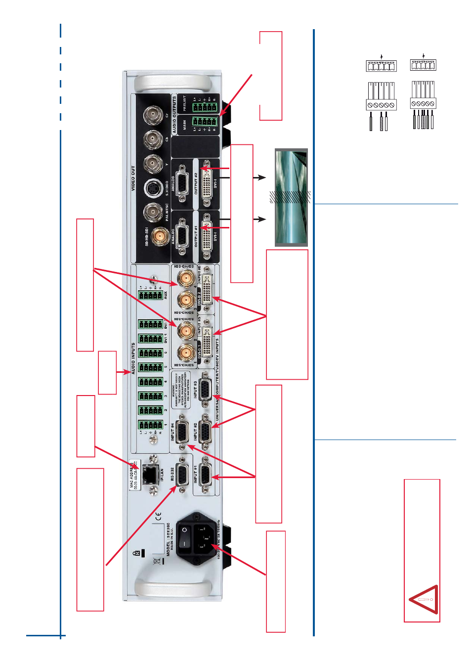
Smart Edge FX - Ref. STE200 Rear Panel Description
Power supply: IEC/EN/UL/CSA
60950-1, internal, autoswitchable
Universal
Analog Computer/TV/HDTV inputs
#1 to #4
SD-SDI/HD-SDI inputs #1 to #4: female BNC
DVI connectors: DVI-D inputs #1 and #2 on
the DVI-I digital pins, and Universal
Analog
inputs #5 & #6 on the DVI-I analog pins.
Use the included break-in cable.
IP-LAN connectors
Audio inputs
HOME MENU
The Home Menu is the system’
s
top level menu, from which
a
ll
o
th
e
rs
m
e
n
u
s
c
a
n
b
e
accessed.
T
o
access a menu, press the [MENU] button.
T
o
navigate in the Home
0HQX
SOHDVH
XVH
WKH
NQRE
7R
F
RQ¿UP
SOHDVH
XVH
WKH
>ENTER] button.
Y
o
u can also
return to the Home Menu by pressing the [EXIT] button.
-
INPUT
:
FRQ¿JXUHWKHLQGLYLGXDOLQSXWW\SHVDQGUHVROXWLRQV
-
OUTPUT #1:
display the left image
-
OUTPUT #2:
display the right image
- VIDEO OUT
:
VHOHFWWRFRQ¿JXUH9
LGHRRXWSXWFDUGVHWWLQJV
-
PRESET
:
store and use presets
-
IMAGE:
change source image settings of an input
-
AUDIO:
access all audio input and output parameters
-
CONTROL:
access device software information, LAN settings, reset factory settings,
amongst other user oriented functions (see next page)
WORKING WITH STE200
The features of STE200 can be controled by the external remote control as:
- Orchestra - Ref.: ORC50
-
Axion2 - Ref.:
ARC200
- Remote Control Software - Ref.: RCS (supplied)
-
T
riple Remote Control Keypad - Ref.:
TRK-800
- Remote Control Keypad - Ref.: RK-300
AUDIO OUTPUT
RK-300, TRK-800 & RCS
can not be used in multiple
machine mode.
!
LEFT
RIGHT
Outputs #1 & #2: female HD15, DVI-I
(simultaneous analog and digital outputs)
Main
Audio Output (balanced)
Prelist
Audio Output (balanced)
RS-232 communication port on a DB9 female
connector or
TCP/IP
on RJ45 connector
AUDIO INPUT/OUTPUT CONNECTIONS
L+
L-
R+
R-
UNBALANCED
Le
ft
Right
GROUND
L+
L-
R+
R-
BALANCED
L+
R+
L-
R-
GROUND(S)
MCO male connectors
Inputs #1 to #6: Balanced & unbalanced connection
Inputs DVI #1 to DVI #2: Balanced & unbalanced connection
Input
AUX: Balanced & unbalanced connection
Outputs #1 to #2: Balanced & unbalanced connection