Communication Concepts 2N5194 User Manual
Page 4
2N5194, 2N5195
http://onsemi.com
4
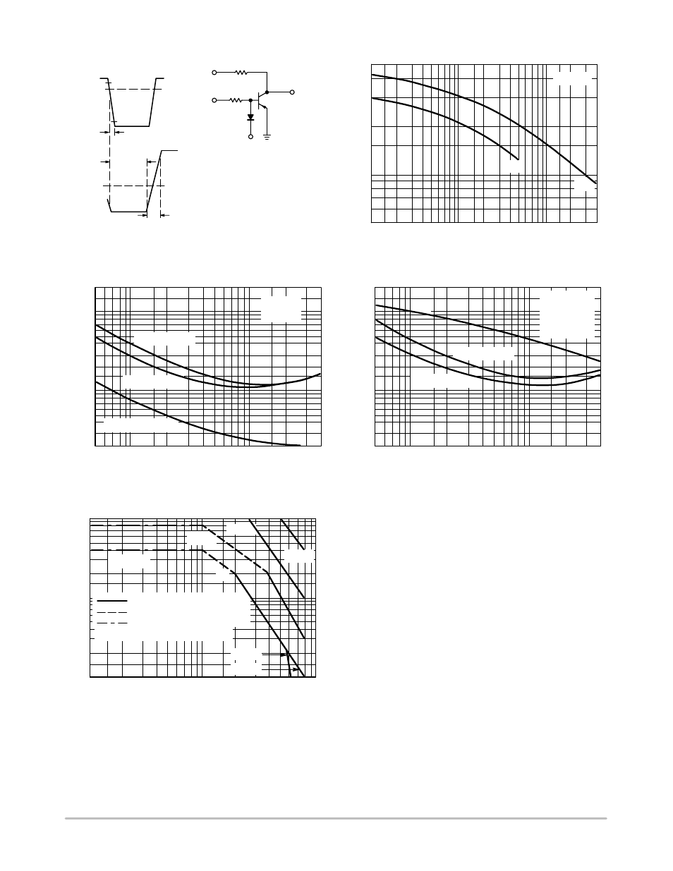
Figure 7. Switching Time Equivalent Test Circuit
APPROX
−11 V
TURN−ON PULSE
V
in
t
1
V
BE(off)
TURN−OFF PULSE
V
in
t
3
t
2
APPROX
−11 V
V
CC
SCOPE
R
B
C
jd
<< C
eb
+4.0 V
t
1
≤ 7.0 ns
100 < t
2
< 500 ms
t
3
< 15 ns
DUTY CYCLE ≈ 2.0%
V
in
R
C
0
R
B
AND R
C
VARIED
TO OBTAIN DESIRED
CURRENT LEVELS
500
0.1
V
R
, REVERSE VOLTAGE (VOLTS)
0.2 0.3 0.5
1.0
3.0
5.0
20
40
300
200
100
70
50
T
J
= 25°C
CAP
ACIT
ANCE (pF)
Figure 8. Capacitance
2.0
10
30
C
eb
C
cb
APPROX
+9.0 V
2.0
0.05
Figure 9. Turn−On Time
I
C
, COLLECTOR CURRENT (AMP)
1.0
0.7
0.5
0.3
0.2
0.1
0.02
0.07 0.1
0.2
0.3
1.0
2.0
4.0
t
r
@ V
CC
= 30 V
I
C
/I
B
= 10
T
J
= 25°C
0.03
t, TIME
(s)μ
0.5
0.05
0.07
0.7
3.0
t
r
@ V
CC
= 10 V
t
d
@ V
BE(off)
= 2.0 V
2.0
0.05
Figure 10. Turn−Off Time
I
C
, COLLECTOR CURRENT (AMP)
1.0
0.7
0.5
0.3
0.2
0.1
0.02
0.07 0.1
0.2
0.3
1.0
2.0
4.0
t
f
@ V
CC
= 30 V
I
B1
= I
B2
I
C
/I
B
= 10
t
s
′ = t
s
− 1/8 t
f
T
J
= 25°C
0.03
t, TIME
(s)μ
0.5
0.05
0.07
0.7
3.0
t
f
@ V
CC
= 10 V
t
s
′
10
1.0
Figure 11. Rating and Thermal Data
Active−Region Safe Operating Area
V
CE
, COLLECTOR−EMITTER VOLTAGE (VOLTS)
5.0
2.0
1.0
0.5
0.1
2.0
5.0
10
20
50
100
SECONDARY BREAKDOWN LIMIT
THERMAL LIMIT @ T
C
= 25°C
BONDING WIRE LIMIT
0.2
I C
, COLLECT
OR
CURRENT
(AMP)
CURVES APPLY BELOW RATED V
CEO
T
J
= 150°C
2N5194
dc
5.0 ms
1.0 ms
100 ms
2N5195
Note 1:
There are two limitations on the power handling ability of
a transistor; average junction temperature and second
breakdown. Safe operating area curves indicate I
C
− V
CE
limits of the transistor that must be observed for reliable
operation; i.e., the transistor must not be subjected to greater
dissipation than the curves indicate.
The data of Figure 11 is based on T
J(pk)
= 150
_C. T
C
is
variable depending on conditions. Second breakdown pulse
limits are valid for duty cycles to 10% provided T
J(pk)
v 150_C. At high−case temperatures, thermal limitations
will reduce the power that can be handled to values less than
the limitations imposed by second breakdown.