Table 2 – parallel capacitance values, Construction hints, Figure 2 – toroid winding pictorial – Communication Concepts FL1 Low Pass Filter User Manual
Page 2
2
Table 2 – Parallel Capacitance Values
Desired Value
Parallel Values
BAND
C1, C2
C1A
C1B
C2A
C2B
(meters)
(pf)
(pf)
(pf)
(pf)
(pf)
160
1653
1500
150
1500
150
80
847
820
27
820
27
40
470
470
--
470
--
20
240
240
--
240
--
15
161
110
51
110
51
10
117
100
18
100
18
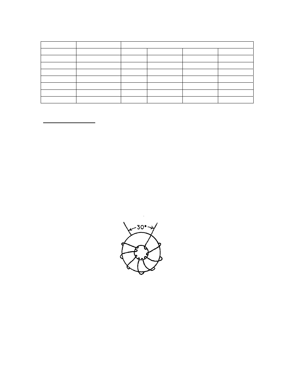
Construction Hints
The effective inductance of a toroid coil depends in part on the distributed
capacitance between the coil turns and between the ends of the winding. The
distributed capacitance should be kept as low as possible. The pictorial
illustration in Figure 2 show the inductor turns distributed uniformly around the
toroid core, but a gap of approximately 30 degrees is maintained between the
ends of the winding. This method is recommended to reduce the distributed
capacitance of the winding. The closer the ends of the winding are to one
another, the greater the unwanted capacitance. Also, in order to achieve the
desired toroid inductance, the winding should be spread over the core as shown
in Figure 2.
Figure 2 – Toroid Winding Pictorial