Mrf154 – Communication Concepts MRF154 User Manual
Page 8
8
Broadband RF Power MOSFET
600W, to 80MHz, 50V
M/A-COM Products
Released - Rev. 07.07
MRF154
• North America Tel: 800.366.2266 / Fax: 978.366.2266
• Europe Tel: 44.1908.574.200 / Fax: 44.1908.574.300
• Asia/Pacific Tel: 81.44.844.8296 / Fax: 81.44.844.8298
Visit www.macomtech.com for additional data sheets and product information.
M/A-COM Technology Solutions Inc. and its affiliates reserve the right to make
changes to the product(s) or information contained herein without notice.
ADVANCED: Data Sheets contain information regarding a product M/A-COM Technology Solutions
is considering for development. Performance is based on target specifications, simulated results,
and/or prototype measurements. Commitment to develop is not guaranteed.
PRELIMINARY: Data Sheets contain information regarding a product M/A-COM Technology
Solutions has under development. Performance is based on engineering tests. Specifications are
typical. Mechanical outline has been fixed. Engineering samples and/or test data may be available.
Commitment to produce in volume is not guaranteed.
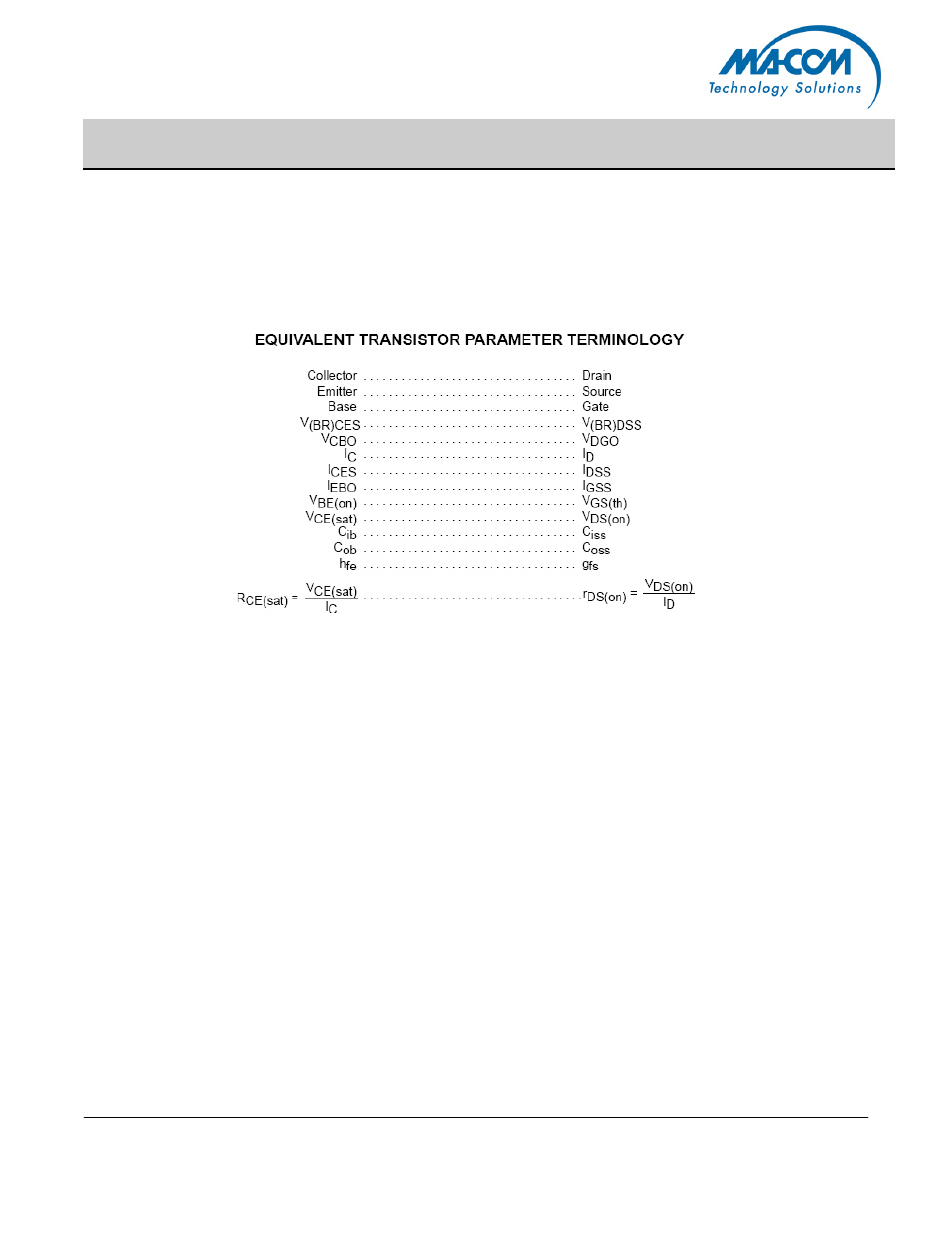
CIRCUIT CONSIDERATIONS
At high power levels (500 W and up), the circuit layout
becomes critical due to the low impedance levels and high
RF currents associated with the output matching. Some of
the components, such as capacitors and inductors must
also withstand these currents. The component losses are
directly proportional to the operating frequency. The manu-
facturers
specifications on capacitor ratings should be consulted on
these aspects prior to design.
Push–pull circuits are less critical in general, since the
ground referenced RF loops are practically eliminated, and
the impedance levels are higher for a given power output.
High power broadband transformers are also easier to de-
sign than comparable LC matching networks.