CHIEF CM2L40 User Manual
Page 8
CM2L40
Installation Instructions
8
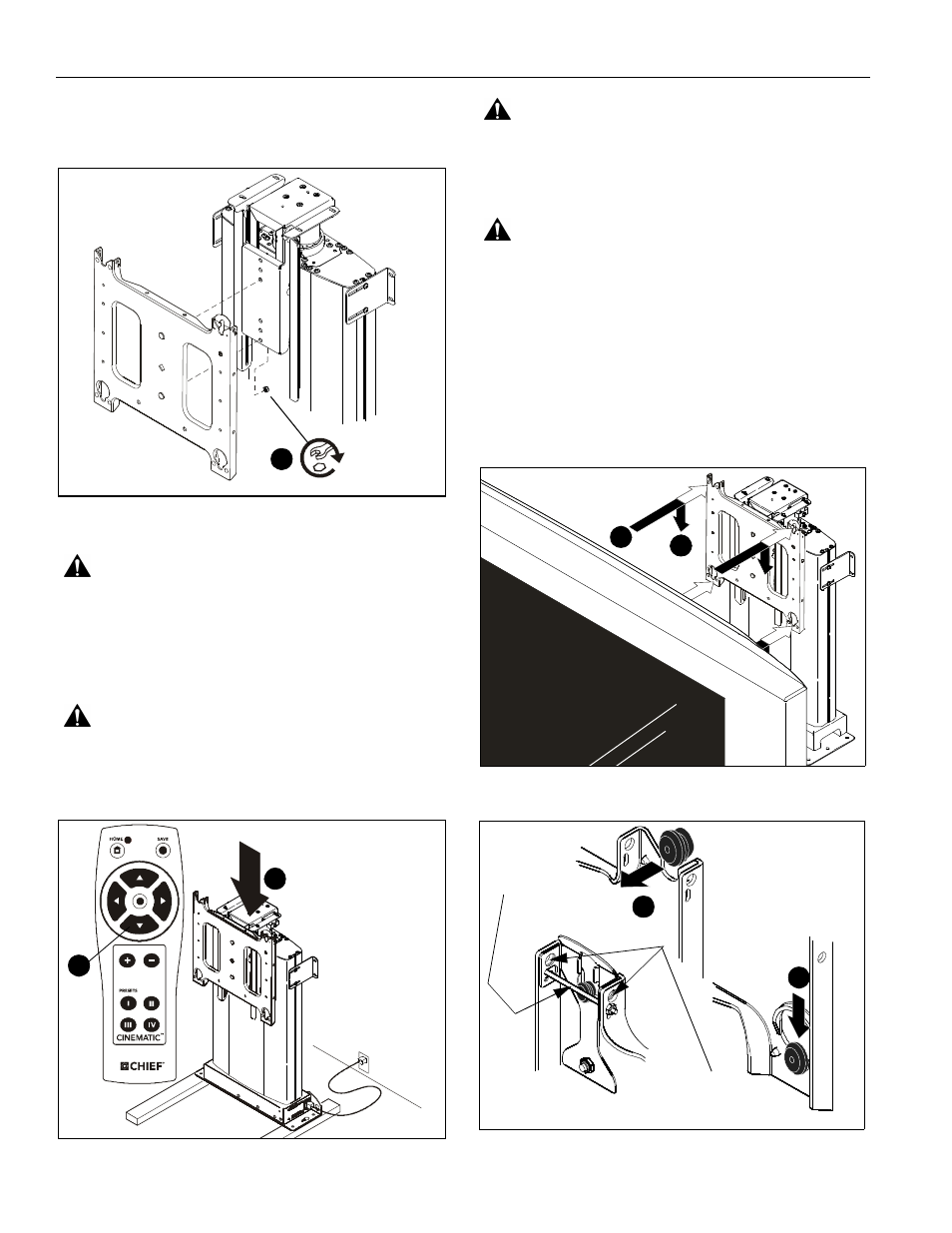
15. Align studs in faceplate with appropriate holes in faceplate
mounting bracket and hang faceplate on bracket with studs.
16. Secure faceplate to faceplate mounting bracket using two
locknuts. (See Figure 7)
Figure 7
Display Installation
WARNING:
EXCEEDING MAXIMUM WEIGHT CAPACITY
CAN LEAD TO SERIOUS PERSONAL INJURY OR AMAGE
TO EQUIPMENT! It is the installers responsibility to ensure
the total amount of weight placed on the mount does not
exceed 190 lbs (86.18 kg), the maximum capacity of the CM2.
1.
If lift was raised during faceplate configuration, lower the lift
until it stops using the remote control.
WARNING:
PINCH HAZARD! FINGERS OR HANDS
BETWEEN MOVING PARTS CAN LEAD TO SEVERE
PERSONAL INJURY! Keep fingers and hands away from
mount when operating.
Figure 8
WARNING:
IMPROPER INSTALLATION CAN LEAD TO
MOUNT FALLING CAUSING SEVERE PERSONAL INJURY
OR DAMAGE TO EQUIPMENT. Displays can weigh in
excess of 40 lbs (18.1kg). ALWAYS use two people and
proper lifting techniques when installing display.
WARNING:
IMPROPER INSTALLATION CAN LEAD TO
MOUNT FALLING CAUSING SEVERE PERSONAL INJURY
OR DAMAGE TO EQUIPMENT. Make sure mounting buttons
on display are properly seated in mounting holes in faceplate.
To install display:
1.
While supporting both sides of display, align four mounting
buttons on display or interface bracket with four mounting
holes in faceplate. (See Figure 9) and (See Figure 10)
2.
Lower display into place listening for audible "click" to ensure
recessed area of mounting buttons are properly seated in
lower area of mounting holes and "click lock" mechanism has
engaged. (See Figure 9) and (See Figure 10)
Figure 9
Figure 10
16
x2
1
1
1
2
2
1
Remove pin
and nuts and
move to lower holes.
A padlock or bolt may
be placed through latch
holes