CEMB USA K10_2 (E) User Manual
Page 5
I 0581 -
5
A
B
Spring
DC
WD
Cone
3
3a
GB
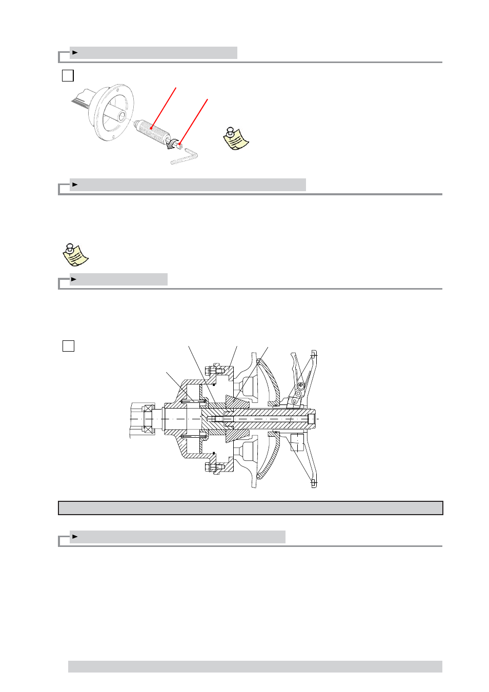
3.3 - Adapter mounting
3.4 - Wheel guard assembly and adjustment (optional)
a) Fasten the components to the base as illustrated in the specifi c exploded drawing.
b) The position of the wheel guard when closed can be adjusted with relative screw accessible at the back. Cor-
rect position is the one which keeps the tube exactly horizontal with the wheel guard closed.
c) Check that the microswitch is held down when the guard is closed.
Note: Do not lean on the guard during the wheel balancing cycle.
3.5 - Spacer WD
When balancing very wide wheels (9”), there is not enough space to turn the distance gauge. To withdraw the
wheel from the machine side, fi t spacer WD on the adapter body and secure it with the standard issue nuts.
When centring the wheel with the cone on the inside, fi t the DC spacer to obtain spring thrust.
4 - CONTROLS AND COMPONENTS
4.1 - Manual rim distance gauge
This gauge serves for manual measurement of the distance of the point of application of the counterweight from the
machine.
The wheel balancing machine is supplied complete
with cone adapter for fastening wheels with central
bore. Other optional adapters can be mounted:
a) Remove threaded end piece A after backing off
screw B.
b) Mount the new adapter (see enclosed brochures).
NOTE: CAREFULLY CLEAN THE COUPLING
SURFACES BEFORE PERFORMING ANY
OPERATION.