Split function, Unbalance resolution), 2 measurement result – CEMB USA ER60 (A) User Manual
Page 11: 4 split function (unbalance resolution)
11
FI
FE
Use and maintenance manual Rev. 09-2013
ENGLISH
5.2
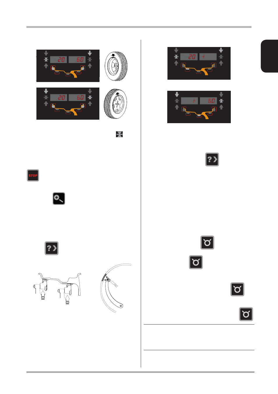
MEASUREMENT RESULT
After performing a balancing spin, the unbalance values
are shown on the displays 1-2. The symbol
indica-
tes the correct angular position of the wheel in order to
apply the counterweights (12 o’clock for clip-on weights;
6 o’clock with laser indication for adhesive weights to be
applied inside the rim).
If the wheel clamp option is enabled (see
MENU
), the wheel
is automatically clamped in the correction position. Pressing
the chuck can be locked/released in any position
to facilitate mounting the wheel (see
MENU
).
If the unbalance is within tolerance, 0 (zero) is display-
ed; pressing
, you can read the values below the
required tolerance threshold.
5.3 EXACT POSITIONING OF THE ADHESIVE
WEIGHT BY MEANS OF THE GAUGE WITH
CLIPS
▪ Press
if using the correction method with adhe-
sive weights on the inside of the rim
▪ Fit the correction weight in the specific gauge seat with
the adhesive part facing upwards
▪ Bring the wheel into correct angular position for the
plane to be corrected
▪ If the wheel clamp option is enabled (see
MENU
),the wheel
is automatically clamped in the correction position.
▪ Pull out the gauge until a correction weight lights up
If the buzzer is enabled (see
MENU
), the attainment of
the weight application distance is accompanied by a
beep.
- INSIDE CORRECTION POSITION
- OUTSIDE CORRECTION POSITION
▪ Rotate the gauge until the correction weight adheres
to the rim
▪ the fact that the weight application position is no
longer vertical is automatically compensated.
To cancel the function, press the
button again.
5.4
SPLIT FUNCTION
(unbalance resolution)
The SPLIT function is used to position the adhesive weights
behind the wheel spokes (angle > 18°) so that they are no
longer visible (for alloy rims). Use this function in the ALU
or STATIC mode where the adhesive weight is applied to
the outer side of the rim.
▪ Perform an unbalance measurement spin.
▪ position the unbalance to be split in the correction
position in order to turn on the laser.
▪ press and hold the button
until the laser points
to the spoke you wish to correct.
▪ release the button
▪ Turn the wheel in the rotation direction indicated by
the positioning arrows until the second spoke is in the
position indicated by the laser and press
▪ position the wheel as indicated by the LEDs. The un-
balance is indicated on the display
To return to the normal unbalance indication press
.
INfoRmATIoN
The spoke-to-spoke distance must be a minimum of
18° and a maximum of 120° (if not, errors 24,25,26 ap-
pear). Spokes with irregular or inconstant angles can be
compensated.
Use of the wheel balancer