5 running the feed – PA Industries Magnum Servo Roll Feed SRF-M12/18/24/32/36/48 - Installation and Operating Instructions User Manual
Page 9
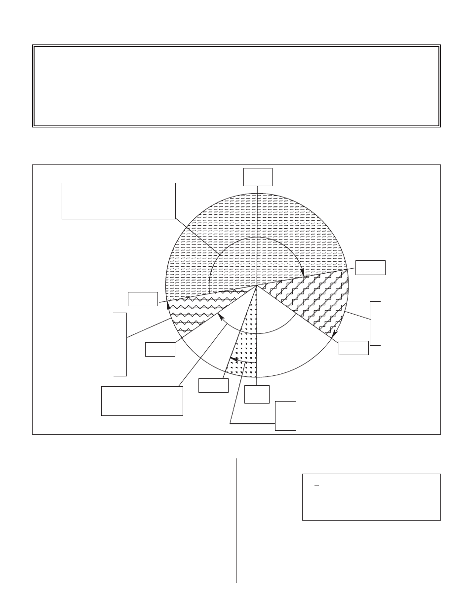
TYPICAL 180 DEGREE FEED ANGLE (FROM 260 DEGREES TO 80 DEGREES)
WITH MECHANICAL PILOT RELEASE:
9
FEED ADVANCE CAM
180° FEED ANGLE
FEEDER STARTS FEEDING AT 260°
AND MUST BE IN POSITION AT 80°
WORKING ANGLE
(PUNCHES IN STRIP)
FEED CAM
“ON”
FEED CAM
“OFF”
FEED MUST BE
“IN POSITION”
SAFETY ANGLE
;
PRESS RAM MUST
STOP IN THIS ZONE
IN EVENT OF A
FEED ERROR
ROLL OPENING
ZONE FOR PNEUMATIC
PILOT RELEASE
DRAWING 17141-02
CONTINUE CAM SIGNAL
CONTINUE CAM
“ON” AT 180°
CONTINUE CAM
“OFF” AT 200°
Figure 5. FEED ANGLE
260°
80°
125°
TDC
0°
180°
BDC
235°
200°
ROLL CLOSING
ZONE;
FEED ROLLS
MUST FULLY CLOSE
IN THIS ZONE
TO PREVENT ROLL
SLIPPAGE AT START
OF FEEDING
5.5 RUNNING THE FEED
NOTE ABOUT CAMS:
The Feed Advance Cam (open tool): The feed
system uses this press cam for timing the feeder
to the press crankshaft. Although no shafting or
belts actually connect the press to the feeder, the
feed must be “told” when it is safe to move the
strip and when the feed move must be completed.
• This “connection” is an electrical one, and not a
mechanical one. This gives the operator/set-up
personnel total flexibility in deciding when the feed
progression should take place.
• Each die set can have a unique “feed angle”. This “feed
angle” is dependent upon many variables; pilot and
punch length, press stroke, strip forming in the die, etc.
All the adjustments to the feed system and press
have now been made. The press is at Top Dead
Center (
TDC
) and ready for automatic cycling.
Proceed by inching the press thru another stroke,
verifying that things are happening at the correct
time (pilot release, feed advance). If the system is
operating properly you can make a few more "hits",
check your parts and then put the press into
continuous mode.
The Magnum Servo Roll Feed will now follow
the press until it is stopped by the Operator,
counter, emergency stop, or feed error.
The display will show:
The speed performance chart (Figure 6) is to be
used as a guide only. Actual feeder/press speeds
may vary depending on factors such as material
thickness, width, rigidity, surface finish, and line
payoff/straightener conditions.
LENGTH
00001.253
COUNT
001000
SPEED
0060/SEC
BATCH RUNNING