PA Industries Magnum Servo Roll Feed SRF-M12/18/24/32/36/48 - Installation and Operating Instructions User Manual
Page 8
8
3. Open the feed rolls with the ‘
OPEN/CLOSE
’
rolls switch on the jog pendant. Insert the material
and close the feed rolls.
4. Adjust the roll clamping pressure via the
pressure regulator located on the material inlet side
of the feed in the top cover. Adjust the pressure
until the liquid filled gage reads approximately
40 psi.
5. Using the ‘
JOG FORWARD
’ button on the jog
pendant, advance the material up to the entrance of
the die (but not too far where the punches would
pierce the material).
6. Check the vertical alignment of the strip. If
necessary, adjust the pass line of the feeder so that
the material is at the proper height.
7. Assuming that the press shut height and the
tool are set up properly, jog the press one or two
strokes without the feed working.
8. Now jog the press down slowly observing when
the longest pilot would engage the pilot hole in the
material if it were there. (Refer to Figure 4.) Note
the press positional readout and put this setting into
your Programmable Limit Switch (
PLS
) for the
‘
PILOT RELEASE TURN ON
’ setting. The ‘
PILOT
RELEASE TURN OFF
’ setting should be 180. (See
Figure 5.)
9. Continue to jog the press slowly until the
longest pilot just comes above the material. Note
the press positional readout and put this setting into
your PLS for the ‘
FEED ADVANCE TURN ON
’
setting. Set the ‘
FEED ADVANCE TURN OFF
’
point approximately 30 degrees less than the pilot
release turn on point. (See Figure 5.)
10. Set the continue cam to turn on at 180 degrees
and to turn off at 200 degrees. This setting should
never need changing. (See Figure 5.)
STRIP
PILOT PIN
Figure 4. PILOT PIN
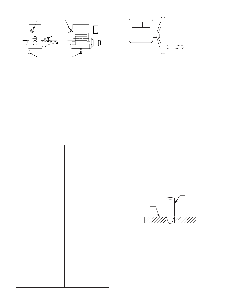
0 0 3 4 0
This reading = 3.40 mm
(.134”) thickness
PASS LINE ADJUST
MATERIAL THICKNESS ADJUSTMENT HANDLE/WHEEL
Figure 3.
Use the following steps to load the feeder:
(Refer to Figure 3.)
1. Record the present settings of the thickness,
feed advance cam, continue cam, and pilot release
cam into a job set-up record sheet for future
reference to the job (see Programmable Limit Switch
Job Set-Up Sheet).
2. Refer to the Thickness Setting Chart shown
below (also located on the feed body near the thickness
adjustment handle). Adjust the material thickness
dial for the proper material thickness. Refer to the
example in the following drawing for proper setting.
Steel Coil Thickness
Mfg. Std.
Inch Equiv.
Metric Equiv.
Dial
Gage No.
for Steel Sheet
mm
Setting
–
.2500
6.35
0063[5]
3
.2391
6.07
0060[7]
4
.2242
5.69
0056[9]
5
.2092
5.31
0053[1]
6
.1943
4.94
0049[4]
–
.1875
4.76
0047[6]
7
.1793
4.55
0045[5]
8
.1644
4.18
0041[8]
9
.1495
3.80
0038[0]
10
.1345
3.42
0034[2]
11
.1196
3.04
0030[4]
12
.1046
2.66
0026[6]
13
.0897
2.28
0022[8]
14
.0747
1.90
0019[0]
15
.0673
1.71
0017[1]
16
.0598
1.52
0015[2]
17
.0538
1.37
0013[7]
18
.0478
1.21
0012[1]
19
.0418
1.06
0010[6]
20
.0359
0.91
0009[1]
21
.0329
0.84
0008[4]
22
.0299
0.76
0007[6]
23
.0269
0.68
0006[8]
24
.0239
0.61
0006[1]
25
.0209
0.53
0005[3]
26
.0179
0.45
0014[5]
27
.0164
0.42
0004[2]
28
.0149
0.38
0003[8]
29
.0135
0.34
0003[4]
30
.0120
0.30
0003[0]
THICKNESS SETTING CHART